![]()
| Study Case | https://doi.org/10.21041/ra.v15i2.808 |
Influence of the mortar placement method on the uniaxial compression behavior of hollow concrete blocks
Influencia de la forma de colocación del mortero en el comportamiento a compresión uniaxial de los bloques huecos de concreto
Influência do método de aplicação da argamassa no comportamento à compressão uniaxial de blocos vazados de concreto
1 Managing Director & Founder, RISE GLOBAL LLC/former EVP Samsung C&T, Chicago, USA.
*Contact author: aabdelrazaq@riseglobal360.com
Received: 03/07/2024
Revised: 21/03/2025
Accepted: 24/14/2025
Published: 01/05/2025
| Cite as: Abdelrazaq, A. K. (2025), “Design and construction of Merdeka 118 tower using high performance concrete: Pushing the boundaries of concrete technology for a megatall building”, Revista ALCONPAT, 15 (2), pp. 175 – 187, DOI: https://doi.org/10.21041/ra.v15i2.808 |
Abstract
This paper presents the structural engineering, construction innovations and key challenges in the design and construction of Malaysia’s next landmark. Merdeka 118 is a large-scale mixed development that includes a 118-storey-679.9m tall mega-tall tower, the second tallest tower in the world. The effective application of High Performance Concrete (HPC) up to C105 has significantly optimized the size of structural elements and improved the economics of the building by maximizing premium floor space. HPC up to C105 has been applied to the mega column and core walls to optimize the size of the elements and improve the gravity and lateral load resisting capability of the elements. To ensure delivery of HPC to the highest standard, extensive planning, testing programs, and quality assurance/quality control (QA/QC) program have been developed. The challenges in Merdeka 118 tower have pushed the boundary of HPC utilization in Malaysia since the Petronas twin towers.
Keywords: high performance concrete, outrigger trusses, belt trusses, supertall buildings, mega concrete columns.
1. General information
The Merdeka 118 Tower is a mega tall building with 118 floors and five basements. Within 292,000 m2 of Gross Floor Area (GFA), the tower consists of 83 office floors [L8-L96], 17 floors of Park Hyatt Hotel [L98-L112 with 252 guest rooms], a 7-story shopping center “118 Mall”, observation deck “The View at 118” located on 115-116 floors, and 5-6 levels of underground parking. The Tower is topped out with 160.4m very slender Spire that includes space for visitors access 360-degree view of the city. Upon completion, Merdeka 118 will stand at 678.90m, making it he the tallest man-made structure in Malaysia and the Southeast Asia region, and the second tallest building in the world after Burj Khalifa. The design of Merdeka 118 is a fusion of modernity and cultural symbolism. While the exterior triangle glass planes of the façade draw inspiration from pattern found in Malaysian arts and crafts, representing the diversity of the Malaysian people. The overall tower design reflects Tunku Abdul Rahaman’s silhouette when raising his hand while chanting “Merdeka” capturing the spirit of independence, freedom, and progress.
2. Lateral load resisting System
The Lateral load resisting system of the tower comprised of 8 Mega Columns, central reinforced core wall system, intermediate steel columns, 6 sets of belt trusses, and 3 sets of outriggers. The central reinforced concrete core wall is linked to 8-mega columns through 3 sets of outrigger trusses in the east-west direction and 2 sets of outriggers in the north south direction to provide the lateral load system of the tower. Due to the slenderness of the tower in the east-west direction and limited structural depth, the lateral load resisting system of the tower is primarily governed by the stiffness requirements rather than strength. The original design offered C85 concrete with local granite aggregate, which has limitations in achieving the required modulus of elasticity, thus requiring significant increase in the mega column sizes per the structural system arrangements or significant increase in reinforcing bars, which resulted in constructability challenges. In lieu of C85 concrete, C105 [with basalt aggregate] is deliberately selected by the General Contractor to significantly increase the modulus of elasticity of concrete, reduce structural steel reinforcement, and improve overall constructability of the project. Figure 2 depicts the arrangement of the lateral and stability mega-frame system of the tower. In addition, this also allowed in balancing the stress level between the mega column, thus significantly reducing the differential shortening between the core wall and mega columns. The Tower is topped out by approximately 169m structural steel spire with significant variation in shape and vented to reduce wind effects.
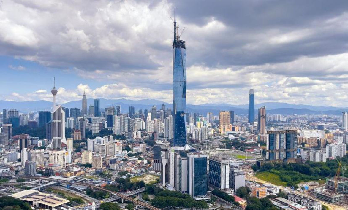
Figure 1. Medeka 118 construction photo with Kuala Lumpur Skyline
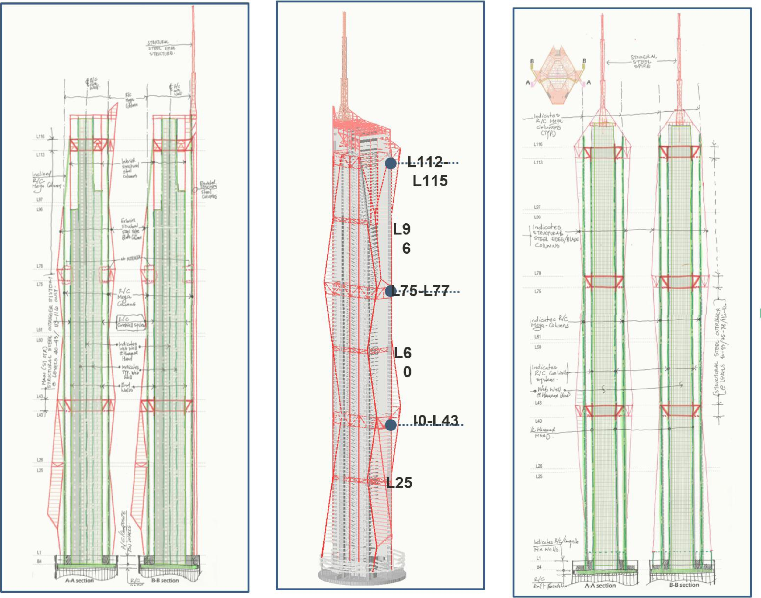
Figure 2a. Merdeka 118: Structural System and lateral & Stability Mega-Frame System
Figure 2b. Merdeka 118: Structural System and lateral & Stability Mega-Frame System
Due to the significant height and slenderness of the spire and limited reach of tower crane, the spire steel structure is constructed using tower cranes from the roof level up to the Tier 4. Temporary strand jack system platform was installed at the Tier 4 level to complete the erection of the remaining 2 top tiers using hydraulic strand jacks by telescoping method.
The Mega frame structure of the Merdeka 118 has many structural challenges that cannot be fully addressed in detail in this paper, but they can be summarized shortly herein, which will addressed and provided in future publications.
The Mega frame consists of centrally located reinforced core wall [with hammer head measuring approximately 7.4m x 4.35m with core flange thicknessed up to 1.7m] that is linked to 8 exterior meg-reinforced concrete columns [.4m x 3.2m] through 8- 3 story – structural steel outriggers at three zones [L40-43, L75-78, L13-116]. Optimizing the design and managing the differential shortening between these elements was critical.
The project is located in hot climate and the structural system has massive structural members. Heat of hydration management and curing for these massive elements is critical.
The project has 6-structural steel belt transfer trusses, supporting structural steel columns) spanning between the mega columns. The differential movement between the mega columns and structural steel columns in between mega columns present issues related to floor levelness and compensation program. Performing detailed construction sequence analysis for the project was of utmost importance as it had direct impact on non-structural components, especially the facade.
The tower is topped out with 169m tall and very slender spire. The spire was assembled within the lower portion of the spire and jacked to final position.
The building is founded on pile supported raft with eight 2.5m composite fin wall linking the core wall to the mega-column to equalize load distribution between the piles. The tower is founded on 4m thick raft foundation on 138 – 2m diameter piles extending approximately 78m below the raft.
Due to the asymmetrical location of the core, the building was expected laterally to move more than 250mm under gravity loads. This had a direct impact on the elevator, and other building systems. Managing the lateral and compensation program was critical.
The project is a very massive site with 5-6 levels below grade and surrounded by facilities with significant historic importance that is founded on shallow foundation and adjacent subway system. Therefore, managing the site’s lateral and vertical movement was of utmost importance. Semi-top-down construction was used over the entire site to manage the building lateral movement. Extensive analysis using 3-D Plaxis and real time monitoring program was implemented to ensure the building movement near the subway remains within 5mm limit.
While all the above challenges cannot be addressed here, the main focus of the paper will be on planning for the concrete works for the project.
3. Planning and Development of C105 concrete with high strength modulus
High performance concrete (C105) with high strength and modulus was successfully developed and applied in Merdeka 118 Tower to minimize the cross-section area and reinforcement of the tower vertical structural elements, thus increasing the usable premium floor space, improving constructability, and providing equivalent structural performance. Refer to Table 1 for concrete grades used for the project.
Table 1. Summary of concrete used for the Merdeka 118
| Location | Floor | Elevation (m) | Grade (MPa) |
| Mega Column | B4 to L1 | 46.35 | 85 |
| L1 to Roof | 556.63 | 105 | |
| Main Core Wall1 | B4 to L1 | 46.35 | 85 |
| L1 to L61 | 304.32 | 105 | |
| L61 to L79 | 381.72 | 80 | |
| L79 to Roof | 561.25 | 60 |
The following provides the results and brief summaries of concrete mix development program, including but not limited to careful planning for concrete works, vigorous material selection, elaborative laboratory and field-testing, large-scale mock-up, and high-rise pumping simulation to attain the targeted high performance and high consistency of concrete. Advanced material technologies were used to achieve targeted strength and minimize concrete temperature from hot weather and mass concreting. Basalt aggregate was specially sourced to achieve the targeted concrete elastic modulus. Bespoke chemical admixture was adopted to achieve desired workability and retention. Extensive laboratory testing and in-situ structure monitoring were conducted to determine reliable elastic modulus, creep and shrinkage coefficients of concrete for more accurate predictions of the tower vertical elements shortening, lateral movement of the tower under gravity loads, and the development of the compensation programs.
4. C105 Concrete Development and testing Programs
The development of C105 high performance concrete with high slump flow, low viscosity, high strength, high modulus of elasticity, minimal heat of hydration for high elevation concrete pumping and in-situ casting of massive element is of great challenge and has never been done in Malaysia. Table 2 below provides a summary of C105’s specific technical requirements set Merdeka 118 to fulfill the structural design and performance requirements.
Table 2. Summary of Concrete C105 Technical Requirements
| Items | Requirements |
| Characteristic Strength | 105MPa for Cube, 95MPa for Cylinder at 56days (Margin +15MPa) |
| Modulus of Elasticity | 40.5 GPa at 28 Days, 45.3 GPa at 91 Days |
| Workability: Slump Flow | 525 – 675mm |
| Temperature | Peak Temp. ≤ 78°C, Differential Temp. ≤ 25°C (Initial targeted temperature 23℃) |
To achieve the C105 concrete required extensive due diligence and careful planning in selecting and sourcing the material to achieve the mechanical and performance requirements specified for the project. The following provides a summary of the material used for Merdeka 118.
Selection of Raw Materials: Most of the raw materials of concrete C105 were locally sourced in Malaysia and their upstream historical test result was studied prior to application. In addition, raw materials were sampled and tested by an independent third-party laboratory to check against compliance conformance during laboratory trial, plant trial and actual production at regular intervals. All the raw materials used in this project were carefully reviewed and selected considering the quality, consistency, and availability to optimize the mix design.
Selection of Cementitious Materials: Cement Manufactured by Lafarge Holcim in Kanthan, Malaysia, the cement conforming to MS EN 197-1 (CEM I 52.5N) was used. The ground granulated blast furnace slag (GGBS) is sourced from Rizhao in China, which is conforming to SS EN 15167-1:2008. The micro silica used for mixes is 920 densified which was manufactured by Elkem in Thailand.
Selection of Aggregate: The fine aggregate is sourced from mining sand from Batang Berjuntai. The fine aggregate is double washed, and the average fineness modulus is 3.2. 14mm sized basalt coarse aggregate originated from Segamat, Johor was also selected for the mix design to achieve high modulus of elasticity concrete with a minimum modulus of 47-49 GPa at 28 days. To verify the consistency and quality of basalt aggregate, rocks were sampled during site visits at the quarry as shown in Figure 3. In addition, petrographic examinations were performed and confirmed that rock samples are fine grained basalt, containing no deleterious minerals, and suitable for C105 concrete.
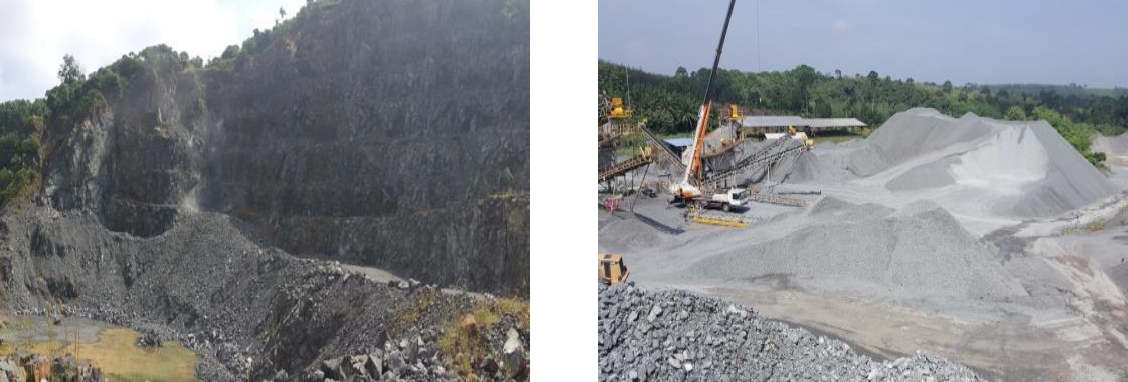
Figure 3. Basalt quarry in Segamat, Johor, Malaysia.
Selection of Admixture: New generation of polycarboxylate polymers (PCE) based superplasticizer was selected. This admixture is specially developed for concrete where fast strength development, high dispersion and retention are required. Application of the admixture is useful for high flowing concrete to be compacted in congested reinforcement areas.
Laboratory and Plant Trail Tests: To optimize the mix design and proportions, numerous raw materials from different sources were identified, and the materials were evaluated by conducting trial tests with different proportion of materials to investigate fresh and hardened properties of concrete. Semi-adiabatic tests were conducted to compare temperature rise of each concrete mix. The temperature rise in concrete C105 was controlled by optimizing total cementitious content, up to 550kg/m3, and utilizing GGBS up to 50% while maintaining silica fume at 10%. Optimum mix proportion was identified under parametric tests by internal laboratory trials and by conducting semi-adiabatic tests. Refer to Table 3 C105 for mix design details.
Table 3. C105 concrete mix design proportions, where S/a is the non-OPC cementitious material ratio and AD is the additional additives for workability.
| Type | W/B (%) | S/a (%) | Unit weight of materials (kg/m3) | AD (Bx%) | ||||
| Water | Binder | OPC | GGBS | Microsilica | ||||
| C105L | 26.3 | 50 | 145 | 550 | 247 | 248 | 55 | 1.85 |
| C105M | 26.3 | 50 | 150 | 570 | 228 | 285 | 57 | 1.55 |
| C105H | 26.3 | 50 | 158 | 600 | 240 | 300 | 60 | 1.35 |
All the laboratory concrete mix designs shown in Table 3 achieved cube compressive strength exceeding 105 MPa at 28 days. Plan trail tests were performed for the same mix design and their tests results for both hardened fresh and hardened concrete are summarized in table 4 and 5.
Table 4. C105 Fresh concrete results.
| Type | Slump flow (mm) | T500 (sec) | ||||
| Initial | 1hr | 2hr | Initial | 1hr | 2hr | |
| C105L | 650/650 | 620/610 | 610/600 | 6.0 | 9.0 | 8.0 |
| C105M | 630/640 | 630/630 | 610/610 | 6.2 | 7.7 | 7.6 |
| C105H | 620/630 | 640/640 | 610/620 | 5.8 | 7.3 | 6.6 |
Table 5. Hardened concrete results
| Type | Compressive Cube Strength (MPa) | Modulus of Elasticity (GPa) | ||||||
| 7 days | 28 days | 56 days | 91 days | 7 days | 28 days | 56 days | 91 days | |
| C105L | 88.2 | 105.1 | 116.1 | 116.4 | 40.9 | 47.0 | 47.9 | - |
| C105M | 86.7 | 109.6 | 111.0 | 114.9 | 44.2 | 48.1 | - | 49.8 |
| C105H | 86.5 | 105.3 | 110.6 | 115.0 | 42.1 | 46.1 | - | 47.9 |
Plant trial results shown in Table 4 confirmed that C105 exhibits consistent slump flow without segregation and bleeding and were within targeted slump flow throughout 2-hour retention. The viscosity of concrete C105 was consistently sustained up to 2-hour retention. Table 5 also depicts that the compressive strength and modulus of elasticity for C105 exceeded 105MPa and 46 GPa at 28 days respectively.
C105 Heat of Hydration Test: Hot block tests were also performed to confirm the concrete temperature rise of C105L, C105M, C105H during the hydration process as shown in Table 6, where L, M and H mean low, medium and high temperatures.
Table 6. Temperature monitoring results of hot block.
| Mix | Temperature (℃) | ||
| Initial | Peak | Temp. rise | |
| C105L | 25.4 | 73.9 | 48.5 |
| C105M | 23.4 | 73.3 | 49.9 |
| C105H | 23.7 | 73.8 | 50.2 |
In addition to the hot bloc tests for all of the C105 concrete mixes, full scale mockup, equivalent to Mega column size [x3200x4300] test was conducted to verify the fresh concrete and the hardened concrete characteristics. Liquid nitrogen was used to lower the temperature of fresh concrete to ensure the initial temperature was within the target before casting. After the de-shuttering work, the thermal blanket was attached at 4 sides and the wet gunny sack was used to cover the top surface for concrete curing as shown in Figure 4.
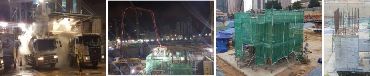
Figure 4. Mega column full scale heat of hydration mock-up.
The temperature rise of the mega-column full scale mock-up was monitored for 14 days using high frequency vibrating wire strain gauges and the data were plotted in real time as shown in Figure 5 and made available to all the stakeholders. The measured peak temperature remained within the 72°C with a maximum temperature differential of 18°C, thus complying with the Merdeka 118 project’s specification requirements. Results from full scale mockup for the mega- column showed that the construction methodology proposed for the mega Column including the formwork type, temperature monitoring plan, temperature control plan, formwork de-shuttering plan and curing plan were successfully achieved. The mega-column full scale mockup construction method, monitoring and curing plans were fully and successfully executed.
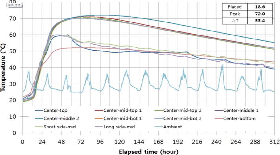
Figure 5. Mega column full scale mockup temperature rise monitoring result.
Concrete Pumping Tests and planning: Pumping high strength concrete in mega tall structure for the construction of vertical member is extremely challenging especially in hot weather country such as Malaysia. In the Merdeka 118 project, C105 was planned to be pumped to 510m using direct pumping, which made it a new world-record. Prior to actual construction, a large-scale pumping test was conducted using a Putzmeister BSA 14000 SHP stationary pump to demonstrate the pumpability of C105 and pump operation skills. Over 550m of horizontal pipeline were installed as shown in Figure 6 and Figure 7 to effectively assess the pipe friction losses, and the effectiveness of the pump pressure demands to deliver the C105 to 510m.
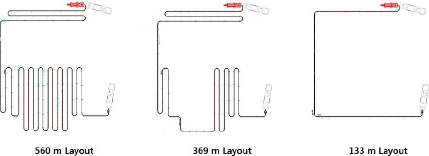
Figure 6. Pipe layout and pressure sensor location.
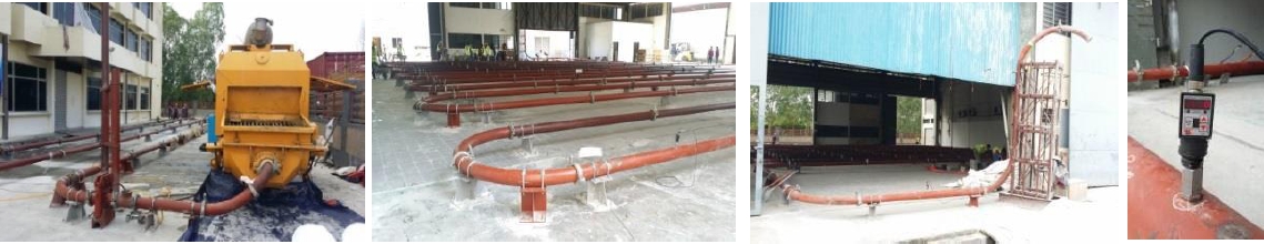
Figure 7. C105 concrete horizontal pipe layout for pumping test.
Concrete C105L, C105M, and C105H with 3 different pipeline lengths were adopted to the pumping test. The pumping pressure and concrete discharging rate was measured and tabulated in Table 7.
Table 7. C105 Concrete pumping test results
| Type | Length (m) | Stroke (no’s) | Hydraulic pressure (bars) | Concrete pressure (bars) | Discharge rate (m3/hr) |
| C105L | 560 | 8.0 | 171 | 102 | 20.4 |
| 10.9 | 250 | 158 | 28.7 | ||
| C105M | 369 | 7.0 | 158 | 96 | 18.5 |
| 13.2 | 261 | 165 | 35.4 | ||
| C105H | 133 | 10.2 | 110 | 55 | 27.4 |
| 17.4 | 154 | 81 | 50.9 |
In addition to determining friction losses, the C105 concrete pumping tests included plans to test the concrete behavior before and after pumping. The C105 concrete pumping test resulted in the following observation, which was considered in planning the concrete pumping works up to 510m.
The concrete slump flow and viscosity reduced after the pumping; this phenomenon is mainly due to the release of entrapped water among cement particles under high pressure pumping.
There was no significant difference in concrete strength or modulus of elasticity before and after pumping.
The concrete temperature increased after the pumping at around 5 to 10°C depending on the pipe length and this was partly due to the environmental heat during the test. The actual increase in the temperature during construction will be significantly lower, based on previous record experiences, since the pipeline will be installed inside the building with lower environmental temperature and shading.
The pipe friction losses were determined from the pump test directly. These friction losses will be equivalent to those of the vertical pipe. To determine the pump capacity, the required pressure will be equal to the stack of concrete weight and the pipe friction losses.
In summary, the C105 concrete pumping test was successful and confirmed that direct pumping to the highest floor at 510m was possible using the and the target concrete discharge rate was confirmed as shown in Table 7.
Planning for Creep and Shrinkage Test: The differential shortening of vertical elements in tall buildings due to concrete elastic, creep, and shrinkage can have adverse impact on the force distribution and serviceability of the building. Thus, to effectively evaluate column shortening due to elastic, creep and shrinkage effects on the vertical elements for Merdeka 118, including the center core wall with hammer head, and the exterior mega-columns, an extensive real time creep, and shrinkage testing programs were put in place to confirm all the mechanical properties of all concrete grades used for the vertical elements of the tower for the evaluation and prediction of column shortening, lateral movement of the tower under gravity loads, and development of compensation program to achieved leveled floors. Creep and shrinkage tests for all concrete materials used in Merdeka 118 Tower vertical elements started on December 7, 2017 with the test variables shown in Table 8 that were directly related to the expected conditions of the tower such as age, exposure conditions, loading level, and testing period.
Table 8. Creep & Shrinkage testing program and variables
| Variables | Type |
| Ages | 28, 56, 90, 180days |
| Exposure | Sealed / Unsealed |
| Loading | 15%, 25% of compressive strength |
| Testing period | 1 year, 3 years |
All of the concrete specimens for the vertical elements were sampled, cured, packed at Merdeka 118 site plant and delivered to an independent laboratory in Korea. Specimens were unpacked and stored in constant humidity & temperature chamber until the intended testing age. Compressive and modulus of elasticity tests of specimens were conducted to evaluate the integrity of specimens and estimate the loading value for creep test. Concrete specimens were prepared and sealed according to exposure conditions prior to loading for creep testing. The primary strain gauges were embedded in the concrete specimen to provide real time measurement of the strain. External demountable mechanical strain gauge (DEMEC) was installed on specimens as reference. All Specimens were loaded continuously according to the loading condition shown in Table 8. For quality control, the measured strain results of concrete C105 specimens were recorded at regular intervals using embedded strain gauge and DEMEC.
State of the art real time monitoring system was set up for the creep and shrinkage testing program, referring to Figures 8 and 9, that was made available to the project team to review and download the strain raw data together with the information on loading, temperature, and relative humidity throughout the testing period. The creep and shrinkage test will be compared with the result from actual field monitoring. The creep and shrinkage test results were analyzed in detail and compared with model codes and used for predicting the columns shortening using detailed construction sequence analysis that reflects the actual construction program. Summary of the construction sequence analysis predictions, actual total strain, and building vertical and lateral movement using the creep and shrinkage parameters from the test result will be published in the future. The creep and shrinkage results were also compared to international standards and model codes and found that there are large variations as shown in Figure 9 below, which will also be discussed in future publications.
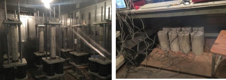
Figure 8. Real time creep & shrinkage tests under fully control environment. Seoul, Korea.
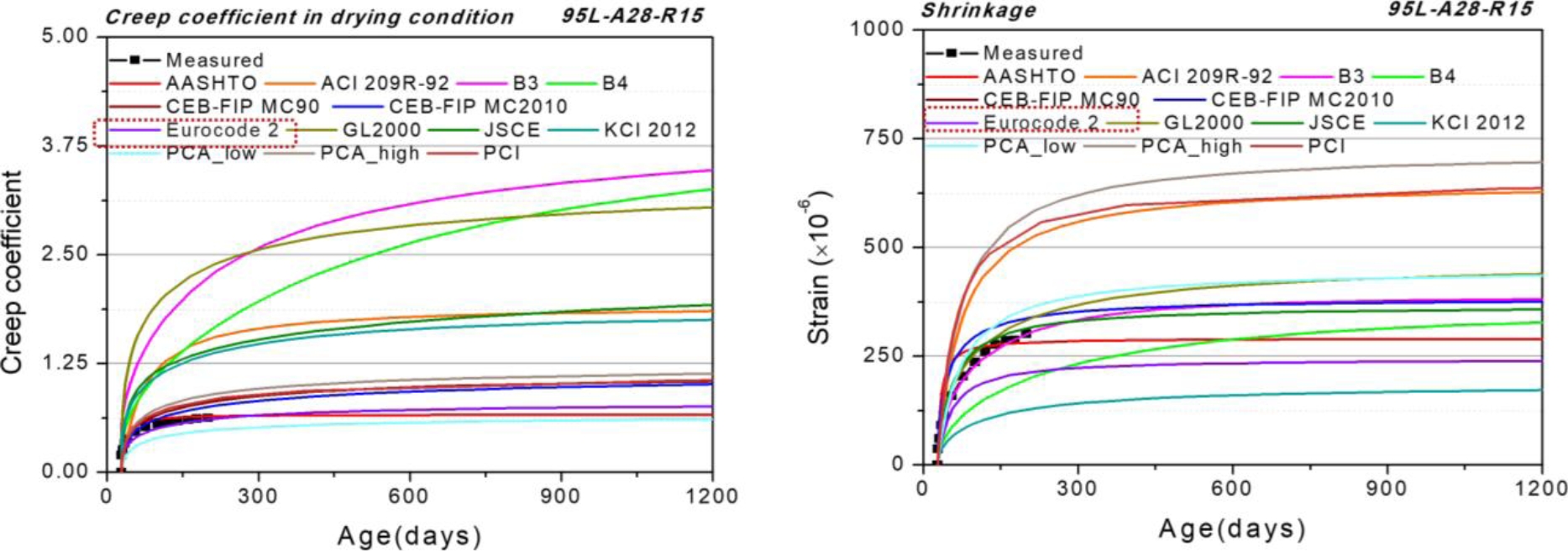
Figure 9. Real time creep & shrinkage tests under fully control environment. Seoul, Korea.
A once in a lifetime experience. A nation building project that all "Anak-Anak Malaysia" will be proud of for generations to come. The Merdeka 118, a mega tall 118 storeys office and hotel tower, with an overall height of 678m. This national icon has become the tallest building in Malaysia, and rank 2nd tallest in the world upon its completion. In Merdeka 118 Tower project, over 80,000 m3 of concrete C105 were successfully poured and pumped up to 510m above ground. The great achievements of developing the concrete C105 with high strength, high modulus of elasticity, high performance, great pumpability by single direct vertical pumping to the top of the skyscraper for massive element in-situ casting, heat of hydration was managed within temperature limit and full compliance with project and design code requirements were first in Malaysia.
5. ACKNOWLEDGMENTS
The successful development and application of high performance concrete C105 to skyscraper, Merdeka 118 Tower were realized by a great teamwork from project team. The authors would like to specially thank PNB Merdeka Ventures Sdn. Berhad, owner of Merdeka 118 Tower, Turner International, Arup Jururunding Sdn Bhd, Construction Technology Group of Samsung C&T Seoul Office, Samsung C&T UEM JV, and Lafarge Malaysia for their contributions to the successful development and application of high performance concrete C105 to the iconic Merdeka 118 Tower.
6. REFERENCES
Abdelrazaq, A. (2013), Early Planning of the Concrete Work at Burj Khalifa, RN Raikar Memorial & Symposium on Advances in Science and Technology of Concrete, American Concrete Institute, 20-21 December 2013.
Ki, J.-H., Lee, S.-H. (2004), Application of High Performance Concrete in Petronas Twin Tower, KLCC (CTBUH Research Paper, CTBUH 2004 Seoul Conference).
Aldred, J. (2010), Burj Khalifa-A New High for High Performance Concrete (ICE Civil Engineering 163) p 77-73.