
| Basic Research | https://doi.org/10.21041/ra.v15i3.800 |
Computational modeling of cracking in autoclaved aerated concrete units and masonry wallets
Modelación computacional del agrietamiento en bloques y muretes de mampostería de concreto celular de autoclave
Modelagem computacional da fissuração em blocos e painéis de alvenaria de concreto celular autoclavado
L. E. Fernández-Baqueiro1* , L. R. Ceballos-Pérez1, J. A. Moreno-Herrera1, J. L. Varela-Rivera1
1 Facultad de Ingeniería, Universidad Autónoma de Yucatán, Mérida, México.
*Contact author: luis.fernandez@correo.uady.mx
Received: 12/03/2025
Revised: 30/07/2025
Accepted: 05/08/2025
Published: 01/09/2025
| Cite as: Fernández-Baqueiro, L. E., Ceballos-Pérez, L. R., Moreno-Herrera, J. A., Varela-Rivera, J. L. (2025), “Computational modeling of cracking in autoclaved aerated concrete units and masonry wallets”, Revista ALCONPAT, 15 (3), pp. 230 – 248, DOI: https://doi.org/10.21041/ra.v15i3.800 |
Abstract
The objective of this research was to study the cracking process of autoclaved aerated concrete (AAC) units and masonry wallets with discrete crack models of the Finite Element Method. The results of an experimental study were analyzed to develop computational models. Models of the splitting tensile strength tests of units and the diagonal tensile strength test of masonry wallets, of different sizes, were developed. Rankine and Mohr failure criteria were considered for the interface elements. The cracking loads were determined. It was concluded that, with the developed models, the cracking loads and the failure mechanism of AAC units and wallets are well simulated compared with what was observed experimentally.
Keywords: autoclaved aerated concrete; masonry; tensile strength; Finite Element Method; discrete crack model.
NOMENCLATURE
| Diagonal area of the wallet | |
| Cohesion of the material | |
| Length of wallet diagonal | |
| Percentage of the wallet diagonal that cracks in the computational model | |
| Modulus of elasticity of the AAC | |
| Modulus of elasticity of the masonry | |
| Failure criterion of the material | |
| Compressive strength of the AAC | |
| Tensile strength of the material | |
| Splitting tensile strength of the AAC | |
| Computational splitting tensile strength of the AAC | |
| Shear modulus of the AAC | |
| Shear modulus of the masonry from the experimental wallet test | |
| Shear modulus of the masonry from the computational wallet model | |
| Height of the AAC unit | |
| Length of the wallet | |
| Computational cracking load of the AAC wallet | |
| Maximum experimental load of the AAC wallet | |
| Maximum experimental load of the AAC unit | |
| Thickness of the AAC unit or wallet | |
| Normal tractions | |
| Shear tractions | |
| Poisson’s ratio of the AAC | |
| Experimental diagonal compressive strength | |
| Computational diagonal compressive strength associated with the computational cracking load of the wallet | |
| Shear strain associated with the shear stress of the wallet | |
| Shear stress associated with a shear strain of the wallet of 0.00005 | |
| Shear stress associated with a 40% of the maximum load of the wallet | |
| Internal friction angle of the material |
1. INTRODUCTION
Masonry is widely used in the construction industry worldwide (Hamid, 2018; Borah et al., 2023). The use of clay and concrete units is common in the construction of masonry elements and structures (e.g. GCM, 2023). However, in México and other countries, the use of autoclaved aerated concrete (AAC) units has increased (Małyszko et al., 2017; van Boggelen, 2018; Varela-Rivera et al., 2018 and 2023). This is because AAC is a lightweight prefabricated material with excellent thermal insulation properties (Costa et al., 2011). In addition, AAC offers advantages in quality control during the manufacturing of units and in the construction of walls when compared to other types of traditional masonry (Varela-Rivera et al., 2024). AAC is a composite material made of Portland cement, lime, silica sand, gypsum, water, and aluminum powder (ASTM C1693-11, 2017). AAC can have a compressive strength that varies depending on its density and composition. In general, the compressive strength of AAC can range from 2 MPa to 6 MPa (ASTM C1693-11, 2017) and its modulus of elasticity between 1300 MPa and 2500 MPa (TMS 402/602, 2022). The Poisson ratio varies between 0.15 and 0.25, a value of 0.20 is recommended in the case of not having experimental data (Aroni et al., 1993). In ASTM C1693-11 (2017), AAC units are classified according to their compressive strength as Class 2, 3, 4, 5 and 6; for example, a Class 4 AAC unit has a compressive strength of 4 MPa.
In general, the mechanical properties of masonry are different from those of the units and the mortar that constitute it (Hamid, 2018). Therefore, individual tests of units, mortars and masonry are required to determine the constitutive behavior and evaluate the quality of each of these materials in terms of their strength (Hamid, 2018). The mechanical properties of masonry are used to predict the strength of masonry walls (SENCICO, 2018; GCM, 2023). For example, the shear strength of confined masonry walls is a function of the diagonal compressive strength of the masonry (Riahi et al., 2009). On the other hand, the Building Code Requirements and Specifications for Masonry Structures of the United States of America (TMS 402/602, 2022) considers the mechanical properties of the units to predict the strength of AAC masonry walls. However, existing codes (e.g. SENCICO, 2018; TMS 402/602, 2022; GCM, 2023) do not provide design equations for AAC confined masonry walls.
In Latin America and other regions of the world, confined masonry is widely used for the construction of houses and other types of buildings due to its low cost and ease of construction (Marques & Lourenço, 2019; Borah et al., 2023). Some researchers have studied the behavior of AAC confined masonry walls subjected to in-plane loads (Varela-Rivera et al., 2018 and 2023; Jasiński & Gąsiorowski, 2023). In these investigations, solid AAC units bonded with thin-bed mortar were considered. The shear and flexural behaviors of this type of walls were studied. In the case of walls with shear behavior, two important events were observed: the lateral load that caused the diagonal cracking on the wall panels and the maximum lateral load. Two types of cracks were mainly observed on the wall panel: diagonal shear cracks and flexure-shear cracks. Diagonal shear cracks are inclined cracks that form within the AAC panel (Varela-Rivera et al., 2018 and 2023; Jasiński & Gąsiorowski, 2023). Flexure-shear cracks begin as horizontal flexural cracks in the vertical confining elements and propagate as inclined cracks within the AAC panel (Varela-Rivera et al., 2018 and 2023). Varela-Rivera et al. (2018 and 2023) developed design equations to determine the shear strength and flexure-shear strength of AAC confined masonry walls, which are associated with the loads that produce the corresponding cracks. The finite element analysis of the principal stress distribution in the walls tested by Varela-Rivera et al. (2018) showed that the orientation of the first cracks is perpendicular to the direction of the principal tensile stresses (Fernández-Baqueiro et al., 2021). Therefore, it is necessary to study the cracking process caused by tensile stresses in AAC units and masonry wallets to subsequently model the shear and flexure-shear cracking in AAC confined masonry walls.
In the experimental tests on AAC confined masonry walls conducted by Varela-Rivera et al. (2018 and 2023), it was observed the propagation of diagonal shear cracks through the units. On the other hand, in the tests conducted by Jasiński and Gąsiorowski (2023), diagonal shear cracks mainly propagated through the mortar joints. The difference in crack location may be associated with the type of thin-bed mortar used. Varela-Rivera et al. (2018 and 2023) used a strong thin-bed mortar with high compressive strength (15.9 MPa and 17.8 MPa, respectively), which complied with ASTM C1660-10 (2018). In contrast, Jasiński and Gąsiorowski (2023) used a weak thin-bed mortar with low compressive strength (6.1 MPa). Cracking in mortar joints has also been observed in other studies conducted on AAC unreinforced masonry walls with weak thin-bed mortar joints (Ferretti et al., 2015; Jasiński & Drobiec, 2016).
The splitting tensile strength tests (ASTM C1006-84, 2001) can be used to study the tensile strength of AAC units. Square wallets can be tested under diagonal compression to determine the tensile strength of AAC masonry (NMX-C-464-ONNCCE, 2010; ASTM E519/E519M-22, 2022). The Mexican standard (NMX-C-464-ONNCCE, 2010) allows to test wallets with dimensions of at least one and a half times the maximum dimension of the unit, while the American standard (ASTM E519/E519M-22, 2022) requires wallets to be at least 120 cm x 120 cm.
The cracks produced by tensile stresses can be computationally simulated with nonlinear models of the Finite Element Method (FEM). Several types of models have been developed, among which the discrete crack model, the smeared crack model and the embedded crack model stands out (Fernández & Ayala, 2004). In the discrete crack model, interface elements are used to simulate cracks, therefore it is used when the possible location of the crack is known (Shi et al., 2014). For example, in the case of masonry structures where cracking occurs in the mortar joint (Ahmed et al., 2019). Mode I (opening) and mode II (in-plane sliding) of Fracture Mechanics (Anderson, 2017) can be modeled with interface elements of a discrete crack model. In the case of masonry, given that it is a material composed of units joined with mortar, different nonlinear modeling strategies have been used (D'altri et al., 2020), including micromodeling, mesomodeling, and macromodeling (Lourenço et al., 1998; Milanesi et al., 2015). In the first approach, the units, the mortar, and the interface between them are explicitly represented. In the second, the unit and the joint are modeled using interface elements. In the third, masonry is modeled as an anisotropic composite material.
Parker et al. (2007) studied the distribution of tensile stresses in units and wallets tests using elastic models of the Finite Element Method (FEM). They observed that tensile stresses are generated in both tests; however, the distribution of tensile stresses in the unit test is more uniform than that in the wallet test. Małyszko et al. (2017) studied the tensile behavior of the AAC testing cylinder and cube specimens, as well as nonlinear finite element models using the Mohr-Coulomb constitutive relationship with isotropic plasticity. They determined the modulus of elasticity and the Poisson ratio and analyzed the failure modes observed in the different tests. Ferretti et al. (2015) studied the behavior of AAC unreinforced masonry walls through experimental tests and nonlinear finite element models. They observed that AAC masonry has a slight anisotropic behavior due to the thin-bed mortar used. They calibrated the macromodel developed by Lourenço et al. (1998) for traditional masonry. Milanesi et al. (2015) studied the behavior of AAC unreinforced masonry infill walls within reinforced concrete frames through experimental tests and nonlinear smeared crack finite element models. They carried out a mesomodeling approach of the masonry. They concluded that the calibrated model satisfactorily reproduces the cracking pattern.
The objective of this research was to study the cracking process in autoclave aerated concrete units and masonry wallets using discrete crack models of the Finite Element Method. Based on the results of an experimental study in which AAC units and wallets were tested (Fernández-Baqueiro et al., 2022), the observed failure mechanisms were analyzed. Models of AAC units were developed, and the tensile strength of the material was calibrated considering a mode I fracture. Models of wallets were developed considering a mode I fracture and different specimen sizes. A model of a 60 cm x 60 cm wallet was developed to simulate the two types of cracks observed in the experimental tests.
2. EXPERIMENTAL STUDIES
The results of an experimental study on the mechanical properties of AAC carried out by Fernández-Baqueiro et al. (2022) were used in this research work. Details of this study can be found in the thesis by Pérez (2019). This study compared the mechanical properties of AAC units and masonry. Solid units of 15 cm x 20 cm x 61 cm (thickness x height x length) and strong thin-bed mortar with a compressive strength of 17.8 MPa were considered. AAC units were Class 4 according to the manufacturer.
Three AAC cubes and three AAC rectangular prisms subjected to axial compression were tested in accordance with ASTM C1693-11 (2017). The compressive strength of AAC was determined using cubes, while the modulus of elasticity was obtained from the rectangular prisms. The cubes were 10 cm per side and the rectangular prisms were 10 cm x 20 cm x 10 cm (thickness x height x length). The tests were carried out using a universal testing machine with a capacity of 600 kN. A load cell was used in the tests as a backup of the loads measured by the universal testing machine. The strains were measured using two linear potentiometers placed on the sides of the rectangular prisms.
Three AAC prisms were tested under axial compression in accordance with NMX-C-464-ONNCCE (2010). The prisms were 15 cm × 61 cm × 40 cm (thickness × height × length) and assembled in stack bond of three AAC units with horizontal thin-bed mortar joints of approximately 3 mm thick. The units used in the prisms were cut along their length, resulting in dimensions of 15 cm x 20 cm x 40 cm (thickness x height x length); this modification aimed to ensure the application of a uniform compressive stress on the prism. The prisms were tested in a loading steel frame, and the loads were applied using a hydraulic actuator. A load cell and pressure transducers were used to measure the loads. Axial deformation was measured over a calibrated length of 40 cm using two linear potentiometers, placing one on each face of the prisms. It was observed that the compressive strength and modulus of elasticity of the masonry, obtained from the test of prisms, were similar to those obtained from the test of cubes () and rectangular prisms (), respectively. The average compressive strength of AAC was 5.28 MPa and the average modulus of elasticity of AAC was 2138 MPa. The average compressive strength of AAC masonry was 5.22 MPa and the average modulus of elasticity of AAC masonry was 2182 MPa.
The splitting tensile strength of AAC was determined by testing five units in accordance with ASTM C1006-10 (2018) (Figure 1). The tensile strength of the AAC () was calculated with Equation (1), which is a function of the maximum load (), the thickness of the unit () and the height of the unit (). The average splitting tensile strength of AAC was 0.46 MPa and the corresponding average maximum load was 21.94 kN.
| (1) |
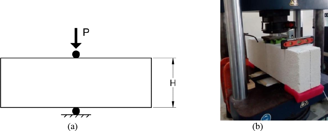
Figure 1. Test to determine the splitting tensile strength of AAC. (a) Test setup. (b) Test view
A square wallet of 15 cm x 120 cm x 120 cm (thickness x height x length) was tested to determine the diagonal compressive strength of AAC masonry in accordance with ASTM E519 (2022). The wallet was built with 6 courses in a half running bond pattern. A strong thin-bed mortar was placed in both vertical and horizontal joints with a thickness of 3 mm approximately. This wallet failed due to AAC crushing in the lower corner (Figure 2a), located above the steel support. Subsequently, smaller wallets were tested to induce cracking associated with tensile stress and to avoid crushing failure. Five wallets of 15 cm x 60 cm x 60 cm (thickness x height x length) were tested. These were built with 3 courses height in a half running bond. A strong thin-bed mortar was also placed at both the vertical and horizontal joints. All the wallets were tested on a loading steel frame, and the loads were applied using a hydraulic actuator. A load cell and pressure transducers were used to measure the loads. The deformations in the diagonals were measured using four linear potentiometers, placing two on each face. Table 1 shows the dimensions of the wallets: length (), thickness () and diagonal (), the diagonal area (), the average of the maximum experimental load (), the average of the diagonal compressive strength () and the average of the shear modulus (). The diagonal compressive strength was calculated with Equation (2). The shear modulus was calculated with Equation (3) according to NMX-C-464-ONNCCE (2010). The diagonal compressive strength of the 120 cm long wallet is not reported because its failure was associated with AAC crushing and shouldn’t be compared with the tensile strength of the units.
| (2) |
| (3) |
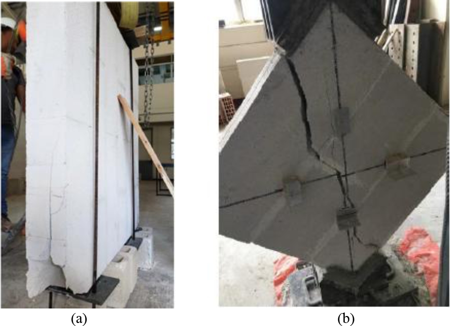
Figure 2. Failure of AAC masonry wallets. (a) 120 cm × 120 cm wallet; (b) 60 cm x 60 cm wallet.
Table 1. Test results of the masonry wallets subjected to diagonal compression.
| (cm) | (cm) | (cm) | (cm2) | (kN) | (MPa) | (MPa) |
| 120 | 15 | 169.7 | 2545.50 | 147.84 | -- | -- |
| 60 | 15 | 84.85 | 1272.75 | 112.84 | 0.89 | 698.63 |
In Equation (3), is the shear stress corresponding to a shear strain of 0.00005, is the shear stress corresponding to 40% of the maximum load and is the shear strain produced by the stress .
Figure 2b presents an example of the final cracking pattern of a 60 cm × 60 cm masonry wallet. As an example, Figure 3 shows two diagrams of the final cracking pattern of 60 cm × 60 cm masonry wallets. These figures illustrate two types of cracking. The first one corresponds to vertical cracks along the diagonal. The second corresponds to inclined cracks. Test results indicated that the final failure mechanism was associated with inclined cracks (Figure 2b). In general, the cracking occurred through the units.
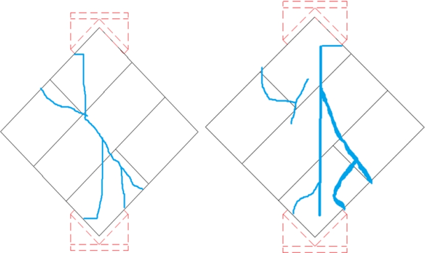
Figure 3. Examples of final cracking patterns in 60 cm x 60 cm masonry wallets.
3. METODOLOGY
The cracking process in AAC units and masonry wallets was simulated using discrete crack finite element models. A linear elastic behavior in the interface elements until failure was assumed. Two failure criteria were considered: Rankine and Mohr. The failure criterion () of Rankine is defined by Equation (4) and is a function of the normal tractions () and the tensile strength of the material (). The Mohr failure criterion () is defined by Equation (5) and is a function of the normal tractions (), shear tractions (), the internal friction angle () and the cohesion (). For simplicity, a brittle behavior was assumed after reaching the selected failure criterion, since AAC is a porous material with a low fracture energy (Aroni et al., 1993) compared to conventional hydraulic concrete (Wittmann and Gheorghita, 1984).
| (4) |
| (5) |
A nonlinear finite element model was developed for an AAC unit of 15 cm × 20 cm × 60 cm (thickness × height × length) subjected to splitting tensile testing (ASTM C1006-84, 2001) (Figure 1). DIANA computer program (DIANA FEA BV, 2025) was used. The computational tensile strength of AAC () that predicts the average experimental maximum load () with the model was determined. Four-node isoparametric quadrilateral plane stress elements with two degrees of freedom per node were used. A structured mesh with an element size of 0.5 cm was used. The AAC unit was modeled considering isotropic behavior with a modulus of elasticity of 2138 MPa and a Poisson ratio () of 0.2. Interface elements were placed along a vertical line at the center of the unit, where the maximum tensile stresses occur. Four-node linear interface elements with two degrees of freedom per node were used. A normal stiffness of 21380 N/mm3 and a shear stiffness of 8554.46 N/mm3 were considered. These stiffness values were calculated assuming an interface element thickness of 1 mm and using the elastic properties of AAC. A Rankine failure criterion with brittle behavior was considered. The degrees of freedom at the center of the unit were restrained at both the top and bottom. Displacement-controlled loading was applied at the top support of the AAC unit. Figure 4 shows the finite element mesh and the support conditions of the AAC unit model.
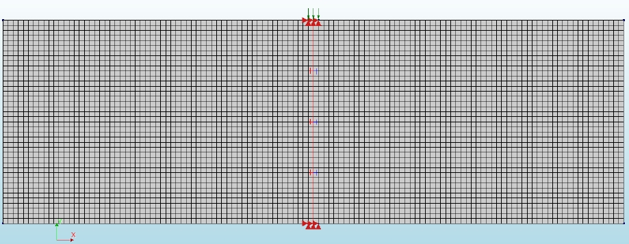
Figure 4. Finite element mesh and support conditions of the AAC unit model.
Nonlinear finite element models of AAC masonry wallets subjected to diagonal compression were developed in accordance with NMX-C-464-ONNCCE (2010) (Figure 2b). Square wallets of different lengths (60 cm, 80 cm, 100 cm and 120 cm) and 15 cm thickness were modeled. The DIANA computer program (DIANA FEA BV, 2025) was used. The computational cracking load () was determined with the computational tensile strength of AAC () obtained from the AAC unit model in the previous step. Quadrilateral plane stress elements with the same properties as in the AAC unit model were used. That is, a macromodeling of AAC masonry was considered, neglecting the thin-bed mortar joints, since it was observed that the modulus of elasticity of AAC was similar to that of AAC masonry. The meshes were generated to be approximately structured with a finite element size of 2.5 cm. Interface elements were placed on a vertical line along the diagonal of the wallet, where the maximum tensile stresses occur. The same properties for the interface elements described in the AAC unit model were considered. The steel supports were modeled considering a modulus of elasticity of 210000 MPa and a Poisson ratio of 0.3. The thicknesses of the finite elements of the steel supports were defined based on the characteristics of the supports used in the experimental tests, as described in ASTM E519 (2022). The degrees of freedom were restricted at the base of the lower steel support. Displacement-controlled loading was applied as a vertical linear displacement at the center of the upper steel support. Figure 5a shows the finite element mesh and the support conditions of the 120 cm long wallet model.
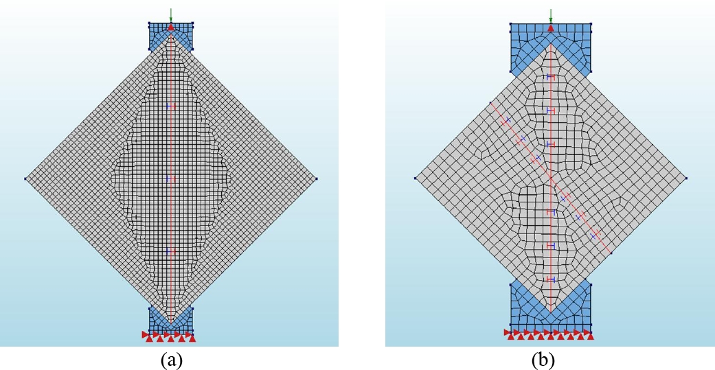
Figure 5. Finite element mesh and support conditions of wallets. (a) Wallet of 120 cm x 120 cm; (b) Wallet of 60 cm x 60 cm.
A new nonlinear finite element model of a 60 cm long wallet subjected to diagonal compression was developed. Interface elements were placed on a vertical line along the diagonal and on an inclined line. These two lines of interface elements are proposed as a simplified approximation of the two types of cracking observed in experimental tests (Figure 3). Cohesion was determined for the Mohr failure criterion used in the interface elements of the inclined line, which was used to predict the average of the maximum experimental load () with the computational model. A brittle behavior was assumed after reaching the failure surface. The internal friction angle was assumed to be (Milanesi et al., 2015). All other characteristics of the model were the same as those of the previous wallets’ models. Figure 5b shows the finite element mesh and the support conditions of the 60 cm long wallet model.
4. RESULTS
4.1 AAC unit
It was determined that a computational tensile strength of AAC () of 0.45 MPa can be used to predict the average experimental maximum load of 21.9 kN. Figure 6a shows the distribution of principal stresses at the center of the unit before cracking. It is observed that the principal compressive stresses have a vertical orientation. Perpendicular to these stresses, in a horizontal direction, there are principal tensile stresses. The principal tensile stresses are not distinguished in Figure 6a because the magnitude of the principal compressive stresses is significantly larger. The direction of the principal compressive stresses corresponds to the orientation of the crack. Figure 6b shows the distribution of normal tractions before cracking, which were obtained from the interface elements. Figure 7 shows the final failure mechanism of the model that was produced by a mode I crack.
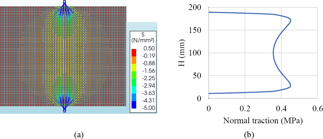
Figure 6. Stress distribution in the AAC unit before cracking. (a) Principal stresses; (b) Normal tractions in the interface elements.
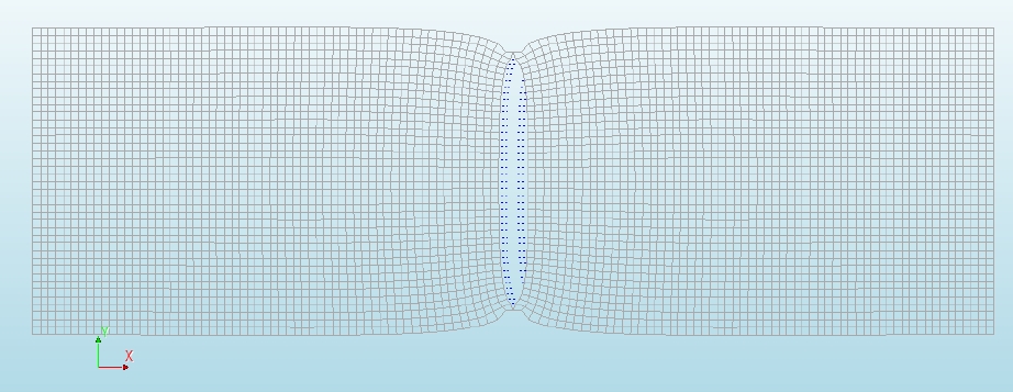
Figure 7. Failure mechanism of the model of the AAC unit.
4.2 AAC masonry
Table 2 presents the length of the wallet (), the length of the wallet diagonal (), the percentage of the length of the wallet diagonal that cracks (), the computational cracking load (), the computational diagonal compressive strength associated with the computational cracking load () and the ratio . The computational cracking load was determined using the computational tensile strength of AAC ( 0.45 MPa) and the model of the wallet with interface elements along the diagonal (Figure 5a). In this model, only cracking of the vertical line was considered; that is, other failure criteria were not included, as a simplification. Figure 8a shows the distribution of principal stresses in the 120 cm × 120 cm wallet before cracking. It is observed that the principal compressive stresses have a vertical direction. The principal tensile stresses are perpendicular to the principal compressive stresses. The principal tensile stresses are not distinguished in Figure 8a because the magnitude of the principal compressive stresses is significantly larger. The direction of the principal compressive stresses corresponds to the orientation of the crack. Wallets with other dimensions have similar stress distributions. Figure 8b shows the distribution of normal tensile tractions along the vertical diagonal before cracking for the different wallet sizes. The normal tractions were obtained from the interface elements. In this figure, the position () has been normalized with respect to the length of the wallet diagonal (). Figure 9 shows the final failure mechanism of the 120 cm x 120 cm wallet model, which corresponds to mode I fracture.
Table 2. Results associated with the computational cracking load of the wallets.
| (cm) | (cm) | (%) | (kN) | (MPa) | |
| 120 | 169.70 | 85 | 171.28 | 0.67 | 1.46 |
| 100 | 141.42 | 79 | 142.81 | 0.67 | 1.46 |
| 80 | 113.13 | 69 | 119.52 | 0.70 | 1.53 |
| 60 | 84.85 | 53 | 99.72 | 0.78 | 1.70 |
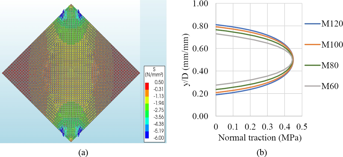
Figure 8. Stress distribution in the wallet before cracking. (a) Principal stresses; (b) Normal tractions in the interface elements.
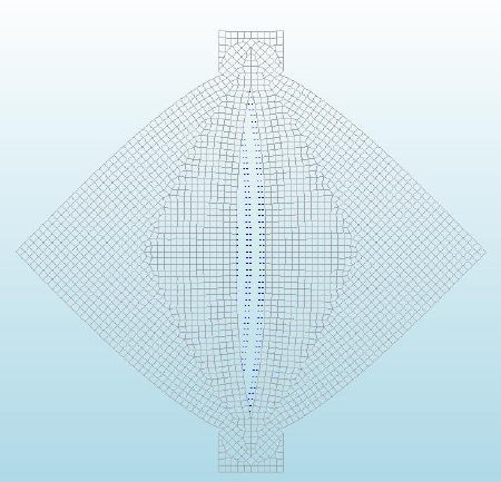
Figure 9. Failure mechanism of the 120 cm x 120 cm wallet model.
It was determined that a cohesion of 1.06 MPa for the Mohr failure criterion predicts the average of the experimental maximum load of the wallets of 60 cm x 60 cm. This failure criterion was used in the interface elements of the inclined line of the wallet (Figure 5b). Figure 10 presents the experimental (M1 to M5) and computational (Mc) shear stress–shear strain curves for the 60 cm x 60 cm wallet. The computational model initially presents a linear elastic behavior until the formation of the vertical crack along the diagonal that is associated with a shear stress of 0.78 MPa, which corresponds to 88% of the experimental diagonal compressive strength. The formation of the crack produces a significant increment of the shear strains; the model overestimates the opening of the vertical crack and the corresponding deformations. Subsequently, the model continued to carry out loads until he formation of the inclined crack at a shear stress of 0.90 MPa, which is similar to the experimental diagonal compressive strength. The final failure mechanism was associated with the formation of the inclined crack, which corresponded to a mode II fracture. The computational shear modulus of the masonry (), calculated with Equation (3), was 640.90 MPa. was calculated considering the linear displacements in nodes close to the measurement points of the deformations of the experimental test.
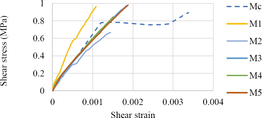
Figure 10. Shear stress – shear strain curve for 60 cm x 60 cm wallets.
Figure 11a shows the distribution of principal stresses in the 60 cm x 60 cm wallet after the formation of the vertical crack on the diagonal and prior to the formation of the inclined crack. The principal compressive stresses have a vertical orientation, causing the interface elements along the inclined line to present both compressive and shear tractions. Figure 11b presents the final failure mechanism of the model, which corresponds to a vertical crack in the diagonal in mode I and an inclined crack in mode II.
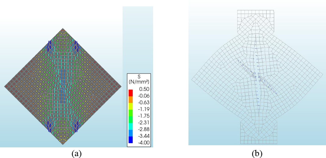
Figure 11. Principal stress distribution and final failure mechanism of the 60 cm x 60 cm wallet. (a) Principal stresses; (b) Failure mechanism.
5. DISCUSSION
The computational tensile strength of AAC ( 0.45 MPa) was similar to the tensile strength of AAC obtained experimentally and calculated with Equation (1) ( 0.46 MPa). This is because Equation (1) is a good approximation of the maximum tensile stresses of the unit. Using the discrete crack model of the FEM, considering a vertical line of interface elements with a Rankine failure criterion, the cracking load and failure mechanism of the AAC unit subjected to splitting tensile testing are well simulated compared with the experimental results. The failure mechanism of the unit was associated with a mode I crack.
The diagonal compression test on a wallet induces tensile stresses along the diagonal, which may lead to the formation of a vertical crack associated with a mode I. On the other hand, the steel supports generate compressive stresses at the ends of the diagonal. By increasing the size of the wallet, both the percentage of the diagonal length under tension (Figure 8b) and the length of the crack may increase; moreover, the ratio tends to 1.46 (Table 2). In the experimental test of the 120 cm x 120 cm wallet, a crushing failure of the AAC was observed in the support at a load of 147.84 kN (Table 1). It was obtained with the discrete crack models that the load necessary to produce the diagonal cracking of the wallet is 171.28 kN (Table 2), which is greater than the experimental maximum load. It is concluded that it is not possible to determine the diagonal compressive strength of AAC masonry using 120 cm × 120 cm wallets, as specified in ASTM E519 (2022), when these are built with units with a compressive strength of 5.28 MPa and strong thin-bed mortar. To generalize this conclusion to wallets built with AAC unit of other classes, it should be considered that the tensile strength of AAC is proportional to the square root of its compressive strength (TMS 402/602, 2022). For example, a change from Class 4 to Class 2 decreases the compressive strength to 50% and the tensile strength to 71%. Therefore, wallets made with AAC units with compressive strength similar to or lower than that considered in this study (i.e. Classes 2 to 5), will also experience AAC crushing failures.
If the size of the wallet decreases, the percentage of the diagonal length under tension decreases (Figure 8b), as well as the length of the diagonal over which the crack may propagate; additionally, the ratio is variable (Table 2). If the wallet is small (e.g. 60 cm x 60 cm), the vertical crack will form, but will not go through the entire wallet. In this case, the wall will be able to carry out additional load. This behavior is similar to that observed in a confined masonry wall, which can carry out additional load after the formation of the first diagonal crack (Riahi et al., 2009). If the diagonal cracks of the masonry panel extend into the confining elements, then the confined wall will fail (Varela-Rivera et al., 2018). In 60 cm × 60 cm wallet, the final failure mechanism is associated with inclined cracks that pass through the entire wallet. Using the discrete crack model of the FEM, considering two lines of interface elements: a vertical line along the diagonal governed by Rankine failure criterion and an inclined line governed by Mohr failure criterion, the cracking load and failure mechanism of AAC masonry wallets of 60 cm × 60 cm are well simulated compared to what was observed experimentally. The failure mechanism of the wallet, which presented a first vertical mode I crack, was associated with the inclined mode II crack.
It is recommended that the design equations used to determine the shear strength of AAC confined masonry walls with strong thin-bed mortar should be a function of the splitting tensile strength of AAC units. This is because diagonal cracking in this type of walls is associated with a mode I crack that propagates through the units and is consistent with the failure mechanism observed in splitting tensile tests of AAC units. The equations developed by Varela-Rivera et al. (2018, 2023, 2025) satisfy this recommendation. On the other hand, it is not recommended to use the diagonal compressive strength of wallets when it is associated with mode II cracks. Furthermore, the splitting tensile test on AAC units is both more economical and simpler to carry out than the test of a masonry wallet. This recommendation changes the paradigm of calculating the shear strength of confined masonry walls based on the diagonal compression strength of the masonry.
The shear modulus of the AAC () was 890 MPa, given that 2138 MPa and 0.2. The value of is calculated with Equation (6) (Oliver and Aleget de Saracíbar, 2002). This value of the shear modulus was used in the finite element models.
| (6) |
The computational shear modulus of AAC masonry obtained from the model of the 60 cm x 60 cm wallet ( 640.9 MPa) was similar to the corresponding experimental average obtained from wallets of the same dimension ( 698.6 MPa). Both values were calculated with Equation (3). Therefore, it is concluded that (a) the model adequately reproduces the elastic behavior of the AAC masonry wallets; (b) the mechanical properties of AAC units can be used to model AAC masonry. That is, to neglect the presence of the thin-bed mortar joint in the AAC masonry; (c) the behavior of AAC masonry can be approximated as an isotropic material. On the other hand, the fact that the shear modulus used in the finite element models differs from that measured in the wallets (experimental and computational), indicates that the diagonal compression test is not a pure shear test, and that Equation (3) only provides an approximation of the shear modulus of masonry. In contrast, tests on traditional masonry wallets made of concrete or clay units subjected to diagonal compression have shown that the shear modulus is approximately 20% of the modulus of elasticity of masonry () (GCM, 2023), whereas the theoretical value is 40% () when assuming a Poisson ratio of 0.25. This difference has been attributed to the anisotropic behavior of these types of masonry.
6. CONCLUSIONS
In this research, the cracking process in AAC units and masonry wallets was studied with discrete crack models of the Finite Element Method (FEM). The results of the computational models allowed us to understand the results of the corresponding experimental tests. Based on the results of this research, the following conclusions are formulated:
The cracking load and failure mechanism of AAC units subjected to splitting tensile testing are well simulated with the discrete crack model compared to what was experimentally observed. This model considered a vertical line of interface elements with a Rankine failure criterion. The failure mechanism of the AAC unit was associated with a mode I crack.
The discrete crack models showed that the load required to produce the diagonal cracking in the 120 cm x 120 cm wallet is greater than the experimental maximum load that produced AAC crushing. Therefore, it is not possible to determine the diagonal compressive strength of AAC masonry using 120 cm x 120 cm wallets as specified by ASTM E519 (2022). This conclusion is valid for wallets made with AAC units corresponding to Classes 2 to 5 and strong thin-bed mortar.
The cracking load and failure mechanism of 60 cm x 60 cm AAC masonry wallets are well simulated with the discrete crack model compared to what was observed experimentally. In this model, two lines of interface elements were considered: a vertical line along the diagonal governed by Rankine failure criterion and an inclined line governed by Mohr failure criterion. The failure mechanism of the wallet, which presented a first vertical mode I crack, was associated with the inclined mode II crack.
It is recommended that the design equations used to determine the shear strength of AAC confined masonry walls with strong thin-bed mortar should be a function of the splitting tensile strength of the AAC units. This is because diagonal cracking in this type of walls is associated with a mode I crack that propagates through the units and is consistent with the failure mechanism observed in splitting tensile tests of AAC units. This recommendation challenges the paradigm of calculating the shear strength of confined masonry walls based on the diagonal compression strength of the masonry.
7. ACKNOWLEDGEMENTS
The second author acknowledges the Consejo Nacional de Humanidades, Ciencias y Tecnologías (CONAHCYT), for the scholarship granted for her PhD studies in Structural Engineering at the College of Engineering at the Autonomous University of Yucatan. The authors are grateful for the work done by former graduate student Daisy Shamel Pérez Buenfil.
8. REFERENCES
Ahmed, A., Shahzada, K., Muhammad, A.S., Naeem, K.A., Ali, S.A. (2019), Confined and unreinforced masonry structures in seismic areas: Validation of macro models and cost analysis. Engineering Structures. 199, 109612. https://doi.org/10.1016/j.engstruct.2019.109612
Anderson, T. L. (2017), “Fracture mechanics: fundamentals and applications (4th ed.)”. CRC Press, Florida, USA, p. 684.
Aroni, S., de Groot, G. J., Robinson, M. J., Svanholm, G., Witttman, F. H. (1993), “Autoclaved Aerated Concrete - Properties, Testing and Design”. RILEM Technical Committees 78-MCA and 51-ALC. Tayor & Francis, UK, p. 424. https://doi.org/10.1201/9781482271195
ASTM International. (2001), ASTM C1006-84 Standard Specification for Splitting Tensile Strength of Masonry Units. https://www.astm.org/c1006-84r01.html
ASTM International. (2017), ASTM C1693-11 Standard Specification for Autoclaved Aerated Concrete (AAC). https://www.astm.org/c1693-11.html
ASTM International. (2018), ASTM C1660-10 Standard Specification for Thin-bed Mortar for Autoclaved Aerated Concrete (AAC) Masonry. https://www.astm.org/c1660-10.html
ASTM International. (2022), ASTM E519/E519M-22 Standard Test Method for Diagonal Tension (Shear) in Masonry Assemblages. https://www.astm.org/e0519_e0519m-22.html
Borah, B., Kaushik, H. B., Singhal, V. (2023), Analysis and Design of Confined Masonry Structures: Review and Future Research Directions. Buildings. 13(5):1282. https://doi.org/10.3390/buildings13051282
Costa, A. A., Penna, A., Magenes, G. (2011), Seismic performance of autoclaved aerated concrete (AAC) masonry: from experimental testing of the in-plane capacity of walls to building response simulation. Journal of Earthquake Engineering. 15(1): 1-31. https://doi.org/10.1080/13632461003642413
D’altri, A. M., Sarhosis, V., Milani, G., Rots, J., Cattari, S., Lagomarsino, S., Sacco, E., Talli, A., Castellazzi, G., De Miranda, S. (2020), Modeling strategies for the computational analysis of unreinforced masonry structures: review and classification. Archives of Computational Methods in Engineering. 27(4): 1153-1185. https://doi.org/10.1007/s11831-019-09351-x
DIANA FEA BV (2025), “User’s Manual DIANA 10.10”. Netherlands. https://dianafea.com/diana-manuals/
Fernández, L. E., Ayala, G. (2004), Constitutive modeling of discontinuities by means of discrete and continuum approximations and damage models. International Journal of Solids and Structures. 41(5-6): 1453-1471. https://doi.org/10.1016/j.ijsolstr.2003.10.010
Fernández-Baqueiro, L. E., Chim-May, R. U., Varela-Rivera, J. L., Moreno-Herrera, J. A., Parra-Cardeña, R. G. (2021), “Comportamiento a cortante de muros confinados de concreto celular de autoclave” en: Memorias del XXII Congreso Nacional de Ingeniería Estructural, Aguascalientes, México, p. 14.
Fernández-Baqueiro, L. E., Moreno-Herrera, J. A., Varela-Rivera, J. L., Pérez-Buenfil, D. S., Cruz-Escareño, E. E. (2022), “Propiedades mecánicas del concreto celular de autoclave” en: Memorias del XXIII Congreso Nacional de Ingeniería Estructural, Zacatecas, México, p. 10.
Ferretti, D., Michelini, E., Rosati, G. (2015), Mechanical characterization of autoclaved aerated concrete masonry subjected to in-plane loading: Experimental investigation and FE modeling. Construction and Building Materials. 98:353-365. https://doi.org/10.1016/j.conbuildmat.2015.08.121
GCM – Gobierno de la Ciudad de México. (2023). NTCM: Normas Técnicas Complementarias para el Diseño y Construcción de Estructuras de Mampostería. Ciudad de México, México.
Hamid, A. (2018), “Masonry structures: behavior and design (4th ed.)”. The Masonry Society, Colorado, USA, p. 723.
Jasiński, R., Drobiec, L. (2016), Comparison research of bed joints construction and bed joints reinforcement on shear parameters of AAC masonry walls. Journal of Civil Engineering and Architecture.10(12):1329-1343. https://www.davidpublisher.com/index.php/Home/Article/index?id=29682.html
Jasińsk, i R., Gąsiorowski, T. (2023), Comparative Studies of the Confined Effect of Shear Masonry Walls Made of Autoclaved Aerated Concrete Masonry Units. Materials. 16 (17): 5885. https://doi.org/10.3390/ma16175885
Lourenço, P. B., Rots, J. G., Blaauwendraad, J. (1998), Continuum Model for Masonry: Parameter Estimation and Validation. Journal of Structural Engineering. ASCE.124(6):642–652. https://doi.org/10.1061/(ASCE)0733-9445(1998)124:6(642)
Marques, R., Lourenço, P. (2019), Structural behaviour and design rules of confined masonry walls: Review and proposals. Construction and Building Materials. 127:137-155. https://doi.org/10.1016/j.conbuildmat.2019.04.266
Małyszko, L., Kowalska, E., Bilko, P. (2017), Splitting tensile behavior of autoclaved aerated concrete: Comparison of different specimens’ results. Construction and Building Materials. 157:1190–1198. https://doi.org/10.1016/j.conbuildmat.2017.09.167
Milanesi, R., Morandi, P., Magenes, G., Binici, B. (2015), “FEM simulation of the experimental response of AAC masonry infills in RC frames” en: 5th ECCOMAS Thematic Conference on Computational Methods in Structural Dynamics and Earthquake Engineering, Isla de Creta, Grecia. https://www.eccomasproceedia.org/conferences/thematic-conferences/compdyn-2015/3711
Olivella, X. O., Aleget de Saracíbar, C. (2002), “Mecánica de medios continuos para ingenieros”. Ediciones UPC, Barcelona, España.
ONNCCE - Organismo Nacional de Normalización y Certificación de la Construcción y la Edificación. (2010). NMX-C-464-ONNCCE Industria de la Construcción - Mampostería - Determinación de la Resistencia a Compresión Diagonal y Módulo de Cortante de Muretes, así como Determinación de la Resistencia a Compresión y Módulo de Elasticidad de Pilas de Mampostería de Arcilla o de Concreto - Métodos de Ensayo. Ciudad de México, México.
Parker, C. K., Tanner, J. E., Varela, J. L. (2007), Evaluation of ASTM Methods to Determine Splitting Tensile Strength in Concrete, Masonry, and Autoclaved Aerated Concrete. Journal of ASTM International. 4(2):62-73. https://www.researchgate.net/publication/333701275
Pérez, D. S. (2019). Análisis de las propiedades mecánicas del concreto celular de autoclave. Tesis de Maestría, Universidad Autónoma de Yucatán, México.
Riahi, Z., Elwood, K. J., Alcocer, S. M. (2009), Backbone model for confined masonry walls for performance-based seismic design. Journal of structural engineering. 135(6): 644-654. https://doi.org/10.1061/(ASCE)ST.1943-541X.0000012
SENCICO - Servicio Nacional de Capacitación para la Industria de la Construcción. (2018). Norma Técnica E.070 Albañilería. Lima, Perú.
Shi, Z., Nakano, M., Nakamura, Y., Liu, C. (2014), Discrete crack analysis of concrete gravity dams based on the known inertia force field of linear response analysis. Engineering Fracture Mechanics. 115:122 -136. https://doi.org/10.1016/j.engfracmech.2013.10.020
TMS - The Masonry Society. (2022). TMS 402/602: Building Code Requirements and Specification for Masonry Structures (Formerly ACI 530). Colorado, USA.
van Boggelen, W. (2018), History of Autoclaved Aerated Concrete. The short story of a long lasting building material. AAC worldwide. https://www.aircrete.com/aircrete-news/history-of-autoclaved-aerated-concrete-2/
Varela-Rivera, J., Fernandez-Baqueiro, L., Alcocer-Canche, R., Ricalde-Jimenez, J., Chim- May, R. (2018), Shear and flexural behavior of autoclaved aerated concrete confined masonry walls. ACI Structural Journal. 115(5):1453-1462. https://www.concrete.org/publications/internationalconcreteabstractsportal.aspx?m=details&id=51706828
Varela-Rivera, J. L., Fernández-Baqueiro, L. E., Moreno-Herrera, J. A. (2023), Shear and flexural behavior of autoclaved aerated concrete confined masonry walls. ACI Structural Journal. 120(3):207-215. https://doi.org/10.14359/51738511
Varela-Rivera, J. L., Cacep-Rodríguez, J., Fernández-Baqueiro, L. E., Moreno-Herrera, J. A. (2024), Comportamiento a cortante de muros de mampostería confinada de concreto celular de autoclave con diferentes escalas. Revista ALCONPAT. 14(2):157-173. https://doi.org/10.21041/ra.v14i2.725
Varela-Rivera, J. L., Cacep-Rodríguez, J., Fernández-Baqueiro, L. E., Moreno-Herrera, J. A. (2025), Shear Strength of Coupled Autoclaved Aerated Concrete Confined Masonry Walls. Journal of structural engineering. ASCE. 151(3):04024222. https://doi.org/10.1061/JSENDH.STENG-13764
Wittmann, F. H., Gheorghita, I. (1984), Fracture toughness of autoclaved aerated concrete. Cement and Concrete Research. 14(3): 369-374. https://doi.org/10.1016/0008-8846(84)90055-3