
| Basic Research | https://doi.org/10.21041/ra.v15i3.794 |
Diagonal compression of hollow concrete block masonry as an indicator of structural vulnerability
Compresión diagonal de mampostería de bloques huecos de concreto como indicador de vulnerabilidad estructural
Compressão diagonal de alvenaria de blocos de concreto vazados como indicador de vulnerabilidade estrutural
E. F. Hernández1* , E. J. Aguilar Arriola2, H. Martínez3
1 Facultad de Ingeniería y Arquitectura, Universidad Americana, Managua, Nicaragua.
2 Investigador independiente, Managua, Nicaragua.
3 Instituto Tecnológico de Pachuca, Pachuca de Soto, México.
*Contact author: eddisson.hernandez@uam.edu.ni
Received: 06/02/2025
Revised: 07/07/2025
Accepted: 13/08/2025
Published: 01/09/2025
| Cite as: Hernández, E. F., Aguilar Arriola, E. J., Martínez, H. (2025), “Diagonal compression of hollow concrete block masonry as an indicator of structural vulnerability”, Revista ALCONPAT, 15 (3), pp. 335 – 347, DOI: https://doi.org/10.21041/ra.v15i3.794 |
Abstract
The objective of this work was to evaluate the performance of artisanal and semi-industrial blocks, used to make prisms and walls, under vertical and diagonal stresses necessary to determine the structural vulnerability of buildings to seismic hazards. Concrete block masonry constructions are commonly used in the Pacific region of Nicaragua, mainly in housing projects. In 2017, the Ministry of Transportation and Infrastructure published the "Minimum Standard for Design and Construction of Masonry MP-001", as a complement to the National Construction Regulations. However, this standard does not take into account the characteristics and properties of local materials. Concrete blocks prisms and walls were elaborated, and failure types and mechanical performance at later ages were determined. The results showed a tendency to diagonal stress failures in walls, with an average strength (Vm) of 6.7 kg/cm2, higher than those reported in the literature.
Keywords: diagonal compression; hollow concrete block; masonry; vulnerability.
1. INTRODUCTION
Nicaragua is a country frequently affected by earthquakes (whether tectonic, subduction, or surface faulting), which represent one of the main threats to its territory. There is a significant history of damage caused by these events in the Pacific region of the country, such as the earthquakes of 1968 and 1972 in Managua. Because of this, over the years, efforts have been made to improve building codes and regulations, replacing the adobe masonry systems of earlier era with concrete block masonry (now almost entirely).
In addition to the above, there is a high level of structural vulnerability in the country's buildings, especially social housing (Ruíz-Valverde and Morales-Leiva, 2018). Structural vulnerability refers to the susceptibility of the structures that keep the buildings standing in the event of an intense earthquake to possible damage. This includes foundations, columns, walls, beams, and slabs (Bonett-Díaz, 2003).
Structural vulnerability goes beyond a building's exposure to seismic hazards; it can also be affected by other natural phenomena, such as hurricanes, heavy rains, tsunamis, etc., which cause deterioration and reduce the service life of structures.
In Nicaragua, social housing and middle-class housing share the same construction systems and materials (reinforced masonry or confined masonry, and concrete blocks). Managua, the capital, is threatened by frequent seismic events that affect buildings made of cement blocks (Aguilar-Arriola, 2016). Therefore, it is important to evaluate the behavior of these construction systems through tests on prisms or walls. In the case of prisms, the common types of failure that may occur are: vertical cracking, conical failure, crushing of pieces, flexural failure, shear failure, explosive failure, etc. On the other hand, there are three types of typical failures in masonry walls subject to diagonal compression: 1) diagonal tension failure in blocks, which produces a diagonal crack that runs through the pieces, with an approximately straight trajectory; 2) diagonal tension failure in joints, which is caused by a lack of adhesion between the block and the mortar. Its trajectory is staggered approximately in the center of the wall; 3) failure due to slippage, which causes failure between the pieces and the mortar, resulting in the detachment of a horizontal joint (Fernández-Baqueiro et.al., 2009)
For masonry systems, it is necessary to understand the capabilities and behaviors of the materials used, such as concrete (beams and columns in confined masonry), hollow blocks made of cement mortar, and bonding mortar or adhesive, in order to achieve greater durability in buildings. Durability refers to “the ability to resist the effects of time, chemical attack, abrasion, or any other deterioration process” (Hernández, 2017). The strength of the mortar is very important, as it ensures that the blocks are properly fixed and the wall is well consolidated. Different combinations and dosages of mortar can be used to obtain better performance (strength, thermal properties, flexibility, etc.). One way to improve the qualities of mortar is to increase the molding pressure which results in increase of the density and compressive strength. Based on the evolution of compressive strength for varying molding pressure levels, it can be assumed that as pressure continues to increase, strength will continue to increase. However, it has been verified in practice that there is a limit of around 0.40 MPa, above which the cement slurry is lost from the agglomerates, making it impossible to produce them (Argento et.al., 2019).
On the other hand, the blocks and mortar form the unit that is the wall (with or without openings/vents), which is the essence of the masonry system. Blocks made from cement mortar allow for many alternatives for improvement, from the proportion of the mixture, materials, additives used, etc. This is of vital importance, considering the demand for cement mortar-based blocks in the Pacific region of Nicaragua to generate greater production, which is assumed by block factories, mostly artisanal, that produce pieces with differences in compressive strength values.
Although there are a number of results and samples on the compressive strength of block units, there is no data in Nicaragua on tests on prisms and walls, as these were regulated until 2017 by the Ministry of Transport and Infrastructure through the Minimum Standard for Masonry Design and Construction MP-001 (MTI, 2017), which complements the National Construction Regulations. To date, there is no documentation of processes or results in this regard, which is why the Mexican Standard NMX-C-464-ONNCCE-2010 (ONNCCE, 2011) was used as a reference in this work for testing walls and piles. The experiences of tests carried out in other countries on blocks and walls show characteristic behaviors. For example, the failure mode due to masonry slippage (due to weak adhesion between the mortar and the masonry pieces), and also failure due to diagonal stress (Tena-Colunga et.al., 2007).
With regard to the technical and professional quality of Nicaragua's construction sector, while it is true that there are technical and undergraduate programs for training master builders, civil engineers, and architects at various public and private institutions, at the postgraduate level, have no programs focused on materials research, specifically “construction materials” (Hernández, 2017). Therefor, the objective of this study is to determine the vertical and diagonal compressive strength of prisms and low walls made with two types of hollow concrete blocks and to evaluate their relationship with the structural vulnerability of buildings to earthquakes.
2. EXPERIMENTAL PROCEDURE
2.1 Masonry
Masonry is a heterogeneous construction system with two basic components: bricks and mortar. Mortar serves for different functions in this system, one of which is to form a bonding layer for the bricks and the other is to allow for uniform transmission of internal forces. The failure mechanism of masonry depends on the difference in elastic modulus between each brick and the mortar (Freeda-Christy et.al., 2013).
Masonry is a combination of several materials, and its failure depends on multiple factors (Sánchez-Tizapa et.al., 2017) such as:
a) The presence or absence of reinforcing elements, such as horizontal steel, vertical steel, or confinement elements.
b) The shape ratio of the walls.
c) The mechanical, geometric, and physical characteristics of the pieces, including their roughness.
d) The type and magnitude of the stress.
e) The physical and mechanical characteristics of the mortar.
f) Relationship between the mechanical characteristics of the mortar and the pieces.
g) The level of saturation of the pieces at the time of bonding.
As mentioned above, masonry is a crucial part of Nicaraguan construction identity. In addition to being used as enclosure, it is also used in load-bearing walls (as facade elements and others). It is commonly considered “non-structural” and is not taken into account in the process of analyzing the building's response to seismic events. However, when masonry is separated from the structure, there is a risk of overturning due to the loss of the arch effect that allows it to resist lateral forces. At the same time, if the masonry is separated from the structure, it loses its stiffening effect, causing the fundamental period to increase (Pujol and Rodríguez, 2019).
2.2 Materials
Materials commonly used in construction in the Managua department were used to conduct the tests, such as:
Sand – obtained from the Motastepe bank. It was screened through a No. 8 mesh for the preparation of the mortar.
Cement – GU Type Hydraulic Cement was used, which complies with ASTM C1157 (ASTM, 2000).
Mortar – mortar is the mixture used to properly join masonry units, whether hollow or solid. It was mixed according to a 1:3 ratio (1 part cement to 3 parts sand), with a water/cement ratio of 0.6, and a strength of 2500 psi or 176 kg/cm2. According to regulations, the compressive strength must not be less than 120 kg/cm² after 28 days, and the joint in the walls must provide a minimum tensile strength of 3.5 kg/cm² (MTI, 2007).
Hollow cement block – hollow blocks are considered to be units that have a net area of at least 50% of the gross area in their most unfavorable section and a wall thickness of at least 2.5 cm. The different specimens (prisms and walls) were constructed with two types of blocks, which were purchased from a traditional block factory and a semi-industrial block factory. The units were constructed in accordance with the National Building Regulations (MTI, 2007) and have dimensions of 15 x 20 x 40 cm.
2.3 Methodology
The methodology used in this research for the preparation and testing of prisms and walls includes the following stages: (1) selection of two block factories to review the load-bearing capacities of the blocks, (2) selection of specimens, (3) construction and testing of specimens, and (4) analysis of results.
a) Selection of block factories
With the support of the Ministry of Transportation and Infrastructure (MTI), which provided an updated list of registered block factories in the Pacific region, in the vicinity of and within Managua, two factories with a good reputation in the construction industry were selected. One of these was artisanal and the second was semi-industrial. The blocks to be tested were purchased from these factories.
b) Selection of specimens
Each of the blocks used in the different tests was marked in situ at each block factory. They were marked on the day of purchase and remained in the factories for three weeks, following each company's storage and curing procedures. At the end of the three weeks, the specimens were removed and transferred to the laboratory of the National University of Engineering, where they were prepared and tested.
c) Preparation and testing of specimens
In accordance with national standard MP-001 - Minimum Design and Construction Specifications for Masonry and ASTM E519 / E519M (ASTM, 2000), six prisms and seven walls were prepared for testing. The specimens (prisms and walls) were constructed 28 days after the blocks were acquired and cured in the laboratory. Water curing was applied daily for a period of 21 days.
The tests were first carried out on prisms with a vertical arrangement of blocks (with 4 blocks built one on top of the other as indicated in the standard), and then on walls subjected to diagonal compression.
The prism test met the following requirements: the thickness of the prism must be equal to the thickness of the walls of the structure (standard housing construction in Managua), the length of the prism must be greater than or equal to the thickness and length of the masonry unit, and the height must include a minimum of three rows of masonry units (in this case, four rows = four blocks were used). Finally, the ratio between height and thickness must be in the range of 2 to 5 (0.85 / 0.17 = 5) (MTI, 2017).
The wall test met the requirements, as did the prisms. They were built inside a laboratory, replicating the characteristics and procedures of actual construction in the city. For this, master builders were brought in to erect the specimens (Figure 1). The test was carried out on low walls built with the same type of pieces, mortar, and manufacturing technique. Before the test, the corners of the diagonal compression were capped with sulfur, maintaining a separation layer with a maximum thickness of 5 mm. During the tests, the load was applied until the specimens fractured (MTI, 2017).
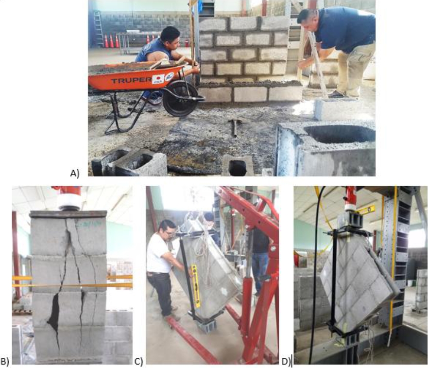
Figure 1. Construction process and testing of prisms and walls.
According to ASTM Standard E519 (ASTM, 2000), at least three specimens made with the same type and size of masonry unit, mortar, and workmanship can be tested. After the test, the diagonal compressive strength values of the specimens (Vm) and their standard deviation were calculated, considering the maximum load applied (Pmax), the thickness of the wall (t), and the length of the diagonal (Lc) (Fernández-Baqueiro et.al., 2009). The walls were tested by subjecting them to a compressive load along their diagonal (Figure 2), and the average shear stress was determined by dividing the maximum load by the gross area of the wall measured on the same diagonal (Tena- Colunga et.al., 2007), which is the result of multiplying the thickness of the wall by the length of the diagonal on which the load is applied.
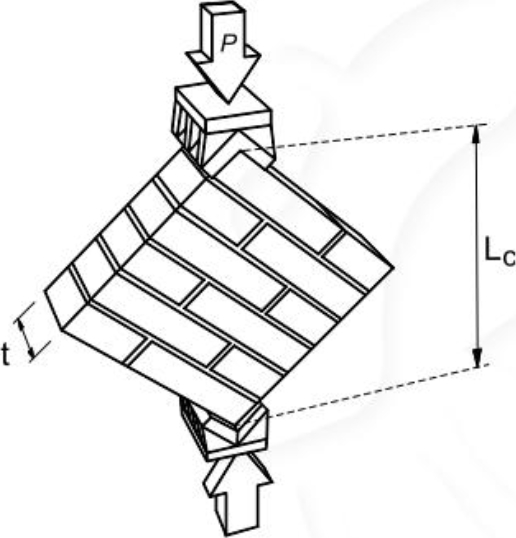
Figure 2. Position of the retaining wall test. NMX-C-464-ONNCCE-2010 (ONNCCE, 2011)
To determine the load applied to the walls, the value of the analog manometer used was recorded, using the following equation (1).
| (1) |
Where:
F= Force or applied load
P= Pressure
A= Effective area of the piston or hydraulic jack (Value)
Based on this conversion, calculations were made of the maximum axial load resisted in prisms and the characteristic resistance of masonry to diagonal compression shear, using equations (2) and (3), respectively. In this work, equation 2 was modified, and three specimens were considered for the calculation instead of five.
| (2) |
Where:
f´m= Basic compressive strength
x= Average compressive strength of the 3 prisms
x3, x1= Highest and lowest resistance values from the tests
| (3) |
Where:
Vm= Diagonal compressive strength
t= wall thickness
Lc= diagonal length
3. RESULTS
3.1 Prism testing
Six tests were carried out on prisms made from concrete blocks purchased from an artisanal and a semi-industrial block factory, with the following results:
In the tests carried out, two types of behavior were observed (Table 1), one involving failure by sliding and the other by collapse. Of the six specimens, four exhibited both behaviors and two exhibited collapses, which occurred immediately due to their low mechanical strength.
Table 1. Types of failures in prism tests.
| N° | Code | Concrete block type | Elaboration Date | Failure type |
| 1 | BE-2-1 | Structural | 11/21/2017 | Sliding/collapse |
| 2 | BE-2-2 | Structural | 11/21/2017 | Sliding/collapse |
| 3 | BE-2-3 | Structural | 11/20/2017 | Sliding/collapse |
| 4 | BNE-1 | Non-structural | 11/21/2017 | Sliding/collapse |
| 5 | BNE-2 | Non-structural | 11/21/2017 | Collapse |
| 6 | BNE-3 | Non-structural | 11/20/2017 | Collapse |
The prisms with lower strength were made with non-structural blocks (handmade blocks), and those with high strength were classified as structural type 2 (BE-2) (semi-industrial blocks).
Tables 2 and 3 show that the compressive strength of the prisms (f´m) was higher in those made with structural blocks than in those made with non-structural blocks. The low error value indicates that these block units have homogeneous compressive strength values.
Table 2. Compressive strength of prisms made of structural blocks.
| N° | Code | Concrete block type | Height (cm) | Thickness (cm) | An/Area (cm2) | P. Initial Failure (kg) | P f. Collapse (kg) | Compressive Strength (kg/cm2) | Elaboration Date |
| 1 | BE-2-1 | Structural | 80.5 | 15 | 1207.5 | 38640 | 44160 | 36.6 | 11/21/2017 |
| 2 | BE-2-2 | Structural | 80.5 | 15 | 1207.5 | 38640 | 44160 | 36.6 | 11/21/2017 |
| 3 | BE-2-3 | Structural | 80.5 | 15 | 1207.5 | 44160 | 52440 | 43.4 | 11/20/2017 |
| Average | 46920 | 38.9 | |||||||
| C | X3-X1 | Standard deviation | 4.0 | ||||||
| 0.431 | 6.9 | f'm= | 35.9 | Error | 10.2 |
Table 3. Compressive strength of prisms made from non-structural blocks
| N° | Code | Concrete block type | Height (cm) | Thickness (cm) | An/ Area (cm2) | P. Initial Failure (kg) | P f. Collapse (kg) | Compressive Strength (kg/cm2) | Elaboration Date |
| 1 | BNE-1 | Non-structural | 80.7 | 15 | 1210.5 | 0 | 19320 | 16.0 | 11/21/2017 |
| 2 | BNE-2 | Non-structural | 80.7 | 15 | 1210.5 | 5520 | 8280 | 6.8 | 11/21/2017 |
| 3 | BNE-3 | Non-structural | 80.7 | 15 | 1210.5 | 0 | 8280 | 6.8 | 11/20/2017 |
| Average | 11960 | 9.93.6 | |||||||
| C | X3-X1 | Standard deviation | 5.3 | ||||||
| 0.431 | 9.1 | f'm= | 5.9 | Error | 53.3 |
3.2 Wall essays
The testing of walls was the conclusion of a process that began in 2017. The testing period for the walls was 950 days. Seven walls were tested, six of them measuring 1 x 1 m and one measuring 80 x 80 cm. For the tests, a loading frame was used, consisting of a hydraulic system comprising a 55-ton Power Team hydraulic jack, with its respective pump and analog pressure gauge, with a capacity of 10,000 psi. Tables 4 and 5 show the results obtained.
Table 4. Diagonal strength of walls made with structural blocks.
| Code | Concrete block | Dimensions (cm) | Thickness t (cm) | Height/Diagonal length Lc (cm) | t*Lc (cm2) | Load (kg) | Vm (kg/cm2) | Test date | Failure type |
| Type | |||||||||
| CA-01 | Structural | 100x100x15 | 15 | 145 | 2175 | 12519.2 | 5.8 | 5/27/2020 | Diagonal tension |
| CA-02 | Structural | 100x100x15 | 15 | 145 | 2175 | 17526.8 | 8.1 | 6/2/2020 | Crushing |
| CA-03 | Structural | 100x100x15 | 15 | 145 | 2175 | 13520.7 | 6.2 | 6/2/2020 | Combined (tension and shear) |
| CA-04 | Structural | 100x100x15 | 15 | 145 | 2175 | 14021.5 | 6.4 | 6/3/2020 | Shear failure- mortar adherence |
| CA-05 | Structural | 80x80x15 | 15 | 117 | 1755 | 12519.2 | 7.1 | 6/5/2020 | Shear failure- mortar adherence |
| Average | 14021.5 | 6.7 | |||||||
| Standard deviation | 0.9 | ||||||||
| Error | 13.3 |
Table 5. Diagonal strength of walls made with non-structural blocks.
| Code | Concrete block | Dimensions (cm) | Thickness t (cm) | Height/Diagonal length Lc (cm) | t*Lc (cm2) | Load (kg) | Vm (kg/cm2) | Test date | Failure type |
| Tipo | |||||||||
| CA-06 | Non-structural | 100x100x15 | 14.5 | 145 | 2102.5 | 11517.63 | 5.5 | 21/5/2020 | Diagonal tension |
| CA-07 | Non- structural | 100x100x15 | 14.5 | 145 | 2102.5 | 3755.74 | 1.8 | 5/6/2020 | Diagonal tension |
| Average | 3.6 | ||||||||
| Standard deviation | 2.6 | ||||||||
| Error | 71.9 |
The data from these tests was collected immediately using a field form that allowed the failure type and the pressure measurement in each case to be recorded. Of the seven walls (six measuring 1 x 1 m and one measuring 0.8 x 0.8 m), three types of behavior were observed: failure due to diagonal stress, failure due to shear-adhesion of mortar, and combined failure (stress and shear). The most common failure was shear failure, which occurred in three walls (two measuring 1 x 1 m and one measuring 0.8 x 0.8 m). One of the specimens tested failed due to crushing (upper block).
The results of the diagonal compressive strength (Vm) were higher in the specimens made with structural blocks compared to the non-structural ones. Similar to what was observed in the f´m values, the error obtained in the low walls made with structural blocks was lower than that of those made with non-structural blocks.
It is important to note that these tests were carried out for the first time at the National University of Engineering, obtaining general data on the failure of retaining walls, especially those built with semi-industrial blocks, classified by the NTON for their resistance in Structural Type 2 (NTON, 2010).
4. DISCUSSION
In the construction industry, it is believed that the strength and durability of masonry structures depend largely on the quality of the bricks. However, the mortar joint also contributes significantly to the compressive strength and durability of the entire structure of a building (Freeda-Christy et. al., 2013). In this regard, it has been shown that a good mortar joint with adequate strength ensures better performance against axial forces. The results suggest different behaviors and average Vm values of 6.7 kg/cm² for structural blocks and 3.6 kg/cm² for non-structural blocks.
The results of the f´m values obtained by Tena et.al., (2017) were similar to those presented in this study. They manufactured 10 prisms for each type of masonry unit and mortar, resulting in a total of 120 masonry samples for compressive strength testing. Under conditions similar to those of this research, in the work of Tena et.al., (2017), the failure recorded in the prisms was due to lateral traction (tension), which starts in the pieces and crosses the mortar joints, which is desirable in good masonry, where the design premise of weak mortar–strong pieces is fulfilled. To calculate the results, they used values of P (maximum axial load resisted), An (gross cross-sectional area of the pile), and an adjustment value for the slenderness ratio (in this case, h/b=3.12) (Tena-Colunga et.al., 2007).
In the case of the sample tested in this research, the average maximum load was P = 46,920 kg for structural blocks and P = 11,960 kg for non-structural blocks, and the basic compressive strength obtained from the procedure suggested in the national regulations resulted in f'm = 35.9 kg/cm2 and f'm = 5.9 kg/cm2, respectively. The behavior was similar in both tests, confirming that type 2 structural blocks have similar capacities to those manufactured in Mexico. Another relevant finding was the reduction in the maximum axial load resisted by the prisms with non-structural blocks, which was four times lower than that of structural blocks.
Similar tests were carried out by researchers in Mexico City on two wall arrangements using two types of units (cement mortar blocks and clay bricks). They reached some important conclusions: the arrangement of the wall is very important in determining diagonal tensile strength, causing differences between the results obtained for the two types of arrangements tested. The differences vary considerably, with the average strength of one of them being only 50% of that obtained in the second. The difference was due to the fact that the dominant failure mode observed in both arrangements was different (Tena-Colunga et.al., 2007).
For walls with arrangement 1, the predominant failure mode was masonry slippage (due to weak adhesion between the mortar and the masonry pieces), while for the low walls with arrangement 2, the predominant failure mode was diagonal stress. Only one of the nine low walls failed due to tangential stresses in the joints. The mortars for walls tested for diagonal compression and other tests (weighing of 30 cubes) had the following characteristics: average volumetric weight of the mortar γj = 1.57 tons/m3, average strength f = 245.7 kg/cm2, coefficient of variation cj = 0.319, and design strength index f*j = 136.6 kg/cm2. The latter was higher than the 125 kg/cm2 established by NTCM-2004 for a type I mortar (Tena-Colunga et.al., 2007).
Another study, in which 12 walls were tested, revealed diagonal compressive strength values ranging from 1.83 to 3.43 kg/cm², with an average value of 2.78 kg/cm² and a coefficient of variation of 0.2, assuming that the diagonal compressive strength follows a normal distribution. It was determined that the diagonal compressive strength of masonry depends on the block-mortar bond, since in all cases failure occurred at the joint. The average shear modulus of the masonry was 16.71 kg/cm², which corresponds to 42% of the average elastic modulus of masonry in the region (Fernández-Baqueiro et.al., 2009).
Figure 3 shows that the diagonal compressive strength of walls with structural blocks was 2.4 times greater than the result obtained by Fernández-Baqueiro et.al., (2009). However, in walls made with non-structural blocks, the results were similar. This demonstrates that the resistance capacity of type 2 structural blocks responds well to axial loads. The failure at the joint is directly related to the joint mortar used to form the wall and, for the purposes of testing the wall, is of great importance in its final behavior under the action of a shear force. The strength indicated in standard MP-001 (MTI, 2017) for joint mortar indicates that there must be a correspondence between the compressive strength of the mortar and the compressive strength of the masonry unit used, but in any case, this value cannot be less than 58 kg/cm².
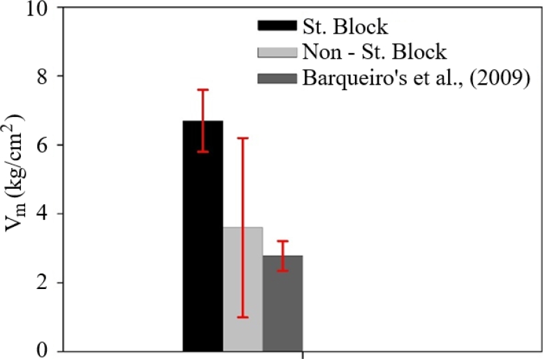
Figure 3. Comparison of diagonal compressive strength results obtained with those of Fernández-Baqueiro et.al., (2009).
The results obtained in this research, when compared to specimens tested by other researchers mentioned in this article, show similarities in behavior and diagonal strength, which, in this case, ranges from 1.8 kg/cm² (non-structural block) to 8.1 kg/cm² (structural block). Another behavior analogous to that shown in the results of Tena et.al., (2017) is shear failure in the bond between the block and the joint mortar, which is a trend and the main cause of failure in walls.
In both, the prism and wall tests, it was found that the specimens built with the handmade block, which correspond to the non-structural type, generally showed more immediate failure tendencies, with even lower strength than that of the adhesive mortar.
5. CONCLUSIONS
The results of this study show three types of wall failure, with shear failure being the most common due to poor mortar adhesion, followed by combined failure and diagonal tension failure. It is noteworthy that 50% of the walls built with Type 2 structural blocks (from a semi-industrial block factory) showed shear failure, while the two walls built with non-structural blocks (from an artisanal block factory) failed due to diagonal tension.
The observed failure patterns and their immediate causes provide valuable information for reducing the structural vulnerability of buildings, which represents a significant effort to mitigate risks, particularly seismic risks in Nicaragua.
The reference values for the diagonal compressive strength of masonry suggest a design value of 1.80 kg/cm², which is lower than the experimental results obtained (6.7 kg/cm²). However, further testing with Type 2 structural blocks from semi-industrial block factories is required to determine this value, taking into account locally available construction materials. These considerations and results contribute to reducing the structural vulnerability of buildings, from the structural design concept and the proper use of materials, particularly for residential buildings.
6. REFERENCES
Aguilar Arriola, E. J. (2016). “Importancia de La Vulnerabilidad Estructural de La Vivienda Unifamiliar En El Riesgo Urbano. Modelo de Estudio Ciudad de Managua, Nicaragua.” Revista de Urbanismo 0(35). https://revistaurbanismo.uchile.cl/index.php/RU/article/view/43090
Argento, R. S., Ferreyra, J., Murdoch Anderson, A, Carrasco, M. F., González, A., Grether, R. M. (2019). “Residuos de Desmote de Algodón Aglomerados: Su Producción y Aplicación En La Construcción de Viviendas.” Ambiente Construído 19(3):127–45. https://doi.org/10.1590/s1678-86212019000300329
American Society for Testing and Materials (2000). Annual Book of ASTM Standards, Section Four, Construction, Volume 04.2 Construction, Concrete and Aggregates. USA: ASTM.
Bonett Díaz, R. L. (2003). “Vulnerabilidad y Riesgo Sísmico de Edificios, Aplicación a Entornos Urbanos En Zonas de Amenaza Alta y Moderada.” Universidad Politécnica de Cataluña.
Fernández Baqueiro, L., Marín Gómez, F., Varela Rivera, J., y Vargas Marín, G. (2009). Determinación de la resistencia a compresión diagonal y el módulo de cortante de la mampostería de bloques huecos de concreto. Ingeniería, Revista Académica de la FI-UADY, 13-2, pp. 41-50, ISSN: 1665-529X.
Freeda Christy, C., Tensing, D., Mercy Shanthi, R. (2013). “Experimental Study on Axial Compressive Strength and Elastic Modulus of the Clay and Fly Ash Brick Masonry.” Journal of Civil Engineering and Construction Technology, 4(4):134–41. https://academicjournals-org.webpkgcache.com/doc/-/s/academicjournals.org/article/article1379608865_Freeda%20et%20al.pdf
Hernández, E. (2017). Construcción durable - Una visión de futuro para Nicaragua. Revista Arquitectura +, 2(4), 8–12. https://doi.org/10.5377/arquitectura.v2i4.9139
MTI. (2007), “Reglamento Nacional de Contrucción.” Ministerio de Transporte e Infraestructura, 156.
MTI. (2017), “Norma Mínima de Diseño y Construcción de Mampostería (MP-001).” Ministerio de Transporte e Infraestructura, 1–58.
NTON. (2010), NTON 12 008 “Materiales de Construcción. Bloque Hueco y Sólido a Base de Cemento y Agregados Pétreos. Requisitos y Evaluación de La Conformidad.”
ONNCCE (2011). NMX-C-464-ONNCCE-2010 - Industria de la Construcción-Mampostería-Determinación de la resistencia a compresión diagonal y módulo de cortante de muretes, asi como determinación de la resistencia a compresión y módulo de elasticidad de pilas de mampostería de arcilla o de concreto. Comité técnico de normalización de productos, sistemas y servicios para la construcción.
Pujol, S., Rodriguez, M. E. (2019). Evaluación del comportamiento de muros no estructurales en edificios de la ciudad de México en el terremoto del 19 de septiembre 2017. Revista Ingeniería Sísmica, (101), 53–66. https://doi.org/10.18867/ris.101.529
Ruíz Valverde, H. Y., Morales Leiva, F. (2018). “Vulnerabilidad estructural en viviendas de interés social hechas con bloques de concreto en managua.” Universidad Nacional de Ingeniería.
Sánchez Tizapa, S., Villaseñor Franco, A., Guinto Herrera, E., Barragán Trinidad, R., Mebarki, A. (2017). Propuesta de valores de referencia para la resistencia de diseño a compresión diagonal y compresión de la mampostería en el estado de Guerrero, México. Revista ALCONPAT, 7(3), 231 - 246. https://doi.org/10.21041/ra.v7i3.159
Tena, A., Liga, A., Pérez, A., González, F. (2017). Propuesta de mejora de mezclas para producir piezas de mampostería de concreto empleando materiales comúnmente disponibles en el Valle de México. Revista ALCONPAT, 7(1), 36-56. https://doi.org/10.21041/ra.v7i1.170
Tena Colunga, A., Juárez Ángeles, A., Salinas Vallejo, V. H. (2007). Resistencia y deformación de muros de mampostería combinada y confinada sujetos a cargas laterales. Revista Ingeniería Sísmica, (76), 29–60. https://doi.org/10.18867/ris.76.58