| Basic Research | https://doi.org/10.21041/ra.v14i3.759 |
Comparison of mechanical behavior of slabs reinforced with GFRP and steel
Comparación del comportamiento mecánico de losas reforzadas con PRFV y acero
Comparação do comportamento mecânico de lajes reforçadas com PRFV e aço
R. Christ1* , H. Z. Ehrenbring2, F. Pacheco2, D. Schneider2, B. F. Tutikian2, G. F. Moreira2, L. Wegher3, O. Beliaev4
1 Department of Civil and Environmental, Universidad de la Costa, Calle 58 #55-66, Barranquilla 080002, Colombia.
2 Polytechnical School, UNISINOS University, São Leopoldo, 93040-230, Brazil.
3 Civil engineering and is the CEO for te Composit Group Brasil, Chapecó, 89801-000, Brazil.
4 State Institute of Commerce, Смольная, 125195, Moscow.
*Contact author: rchrist@unisinos.br
Received: 01/06/2024
Revised: 31/07/2024
Accepted: 02/08/2024
Published: 01/09/2024
| Cite as: Christ, R., Ehrenbring, H. Z., Pacheco, F., Schneider, D., Tutikian, B. F., Moreira, G. F., Wegher, L., Beliaev, O. (2024), “Comparison of mechanical behavior of slabs reinforced with GFRP and steel”, Revista ALCONPAT, 14 (3), pp. 224 - 240, DOI: https://doi.org/10.21041/ra.v14i3.759 |
ABSTRACT
The objective of this study is to evaluate the mechanical behavior of GRFP in massive concrete slabs. The use of glass fiber reinforced polymer (GFRP) rebars in construction design has been an alternative technique to provide more durable structures. However, there is a need to evaluate the behavior of GFRP reinforced slabs under flexure and to compare the service state (SS) and ultimate service state (USS) of the loaded element. Thus, reinforced concrete slabs of varying thicknesses were constructed with steel and GFRP rebars. Results show that the applied load for maximum span deflection of the GFRP slab under SS was 50% lower than for the one with steel reinforcement. The maximum span deflection of the GFRP slab under USS was also 282% larger than for steel rebars reinforcement.
Keywords: GFRP; reinforced concrete; slabs; flexural tensile; mechanical behavior.
1. INTRODUCTION
The use of fiber reinforced polymer (FRP) in structures, both in reinforced concrete or structural elements with varying profile, has been increasing (Satasivam et al., 2018). As a result, studies to evaluate the advantages of FRP reinforced concrete have been conducted in several countries. These studies evaluated the mechanical properties of FRP and its potential effect on performance when incorporated in a structural element (Ahmed et al., 2020; Gajdošová et al., 2020; Gravina et al., 2020; Zhang et al., 2021; Л.И. Бондалетова, 2013). Specific standards for FRP rebars and reinforced structures were developed among the world such as ACI 440.1R-15 (2015), CAN/CSA S806-12 (2012), CNR-DT 206 (2006), GOST 31938 (2014), GOST 30247.0 (1994) and GOST 32486 (2013).
Corrosion is the most relevant degradation mechanism in steel reinforced concrete structures and has the most impact, be it from contact with carbon dioxide or chloride ions (Gajdošová et al., 2020). Steel reinforcements under corrosion degrade, decreasing the structural stability of the entire material (Jabbar; Farid, 2018). This phenomenon by itself demonstrates the importance of FRP reinforcement since it does not corrode and extends the useful service life (USL) of the structure. Studies have already proven that FRP is resistant to alkaline environments such as cementitious matrices (Gravina et al., 2020; Manalo et al., 2020).
On the other hand, since FRP is a composite made up of fibers and resin, a specific combination of materials must be used depending on its application to ensure certain durability characteristics of the element (Bakouregui et al., 2021). into FRP to produce Glass Fiber Reinforced Polymer (GFRP). However, the type of fiberglass used must also be alkali-resistant (Arczewska; Polak; Penlidis, 2021).
Reinforced concrete slabs are important structural elements that absorb and distribute the loads of a building and are subjected primarily to flexure (Mahroug; Ashour; Lam, 2014). Several studies examined the effect of different types of FRP in the behavior of slabs and beams (Ahmed et al., 2020; Ashour, 2006; Barris et al., 2013; Mahroug; Ashour; Lam, 2014; Noël; Soudki, 2014; Satasivam et al., 2018). However, Kaszubska et al. (KASZUBSKA; Kotynia; Barros, 2017) noted that a stumbling block in the use of FRP was that this type of reinforcement rebar had linear-elastic behavior and low modulus of elasticity, which made it prone to fragile rupturing when subjected to a high tensile stress leading to sudden failure.
Steel reinforced concrete projects take advantage of the potential of both materials, that is the compression strength of concrete and tensile strength of steel. In this case, the strength of steel is fully utilized when the reinforcing steel starts yielding and contributes to the ductility of the structure (Shi et al., 2020). In the case of FRP reinforced concrete projects, excessive yielding of the member is undesirable since FRP does not yield, displays a linear elastic behavior and element deformation is larger than steel (Chu; Hossain; Lachemi, 2020).
The deformation of FRP rebars directly affected structural performance and USL (Starkova et al., 2012). There were three stages of FRP deformation. In the first stage, deformation was observed mostly on the resin due to its low modulus of elasticity and redistribution of stresses in the fibers (Shi et al., 2015). The second stage contained a slow increase in deformation due to the constructive characteristics of the rebar such as void spaces in the resin and fiber. The third stage occurred when the rebar stress exceeded 60% of its ultimate stress (Wang et al., 2014).
In the case of GFRP, the ratio between maximum deformation and initial elastic deformation decreased when the applied stress exceeded 30% of its maximum tensile strength (Najafabadi et al., 2018). Mechanical tests on GFRP reinforced slabs subjected to flexure at ambient and elevated temperatures were conducted by Gao et al. (Gao et al., 2020) and Rosa et al. (Rosa et al., 2020). However, these studies focused on the load bearing capacity and final deformation of the elements.
The aim of this study, therefore, is to enhance knowledge on the mechanical behavior of GFRP reinforced slabs of different thicknesses under flexure. Experimental and Analytical studies were conducted to evaluate the SS and USS of GFRP reinforced slabs in comparison with steel. A detailed study on the occurrence of first crack loads for different slab thicknesses was carried out and its relation to the maximum moments was analyzed
2. MATERIALS AND METHODS
Twelve slabs were produced with 3,000 mm in length and 1,100 mm in width. Thicknesses (w) selected were 70 mm, 100 mm and 120 mm. Reinforcement was provided from GFRP rebars 8 mm in diameter and three test slabs set up was done or each slab thickness. For comparison purposes, 3 slabs of 100 mm thickness were manufactured with steel rebars of the same diameter. The test samples were identified as GFRP-70 (w = 70 mm), GFRP-100 (w = 100 mm), GFRP-120 (w = 120 mm) and Steel-100 (w = 100 mm). The slabs with cross sections shown in Figure 1. The concrete strength class was 40 MPa, as recommended in standard C143-20 (ASTM, 2020).
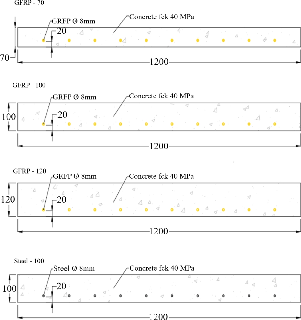
Figure 1. Sample cross section of slabs of this study (dimensions in mm)
Both GFRP and steel rebars had nominal diameters of 8 mm and cross-sectional area of 40.5 mm2. The GFRP rebars were manufactured in a pultrusion process with type E fiberglass fibers impregnated with epoxy resin. The external surface of the GFRP rebars had grooves matching the type of fiber and resin used in manufacturing. Steel rebars were A615/A615M-14 carbon steel. The mechanical properties of the rebars used in this study are shown in Table 1. The GFRP bars were evaluated following the ASTM D7205 standard and the steel bars following the ASTM A615 prescriptions.
Table 1. Mechanical properties of GFRP and steel rebars of this study
| Property | Steel | GFRP |
| Compression strength (MPa) | 500 | 300 |
| Tensile strength (MPa) | 500 | 1,000 |
| Shearing strength (MPa) | 500 | 150 |
| Modulus of elasticity (GPa) | 210 | 50 |
The slabs were subjected to 4-point static flexural bending tests as shown in Figure 2. The load capacity of the apparatus was of 300 kN monitored by a 50 kN load cell of 0.01 kN resolution. Slab deflection was measured with two linear variable displacement transducers (LVDT) with 0.002 mm resolution placed at the ends of the middle of the span. Load and deflection data were recorded with a rate of 10 Hz. Test methodology was prescribed displacement at a rate of 5 mm/min.
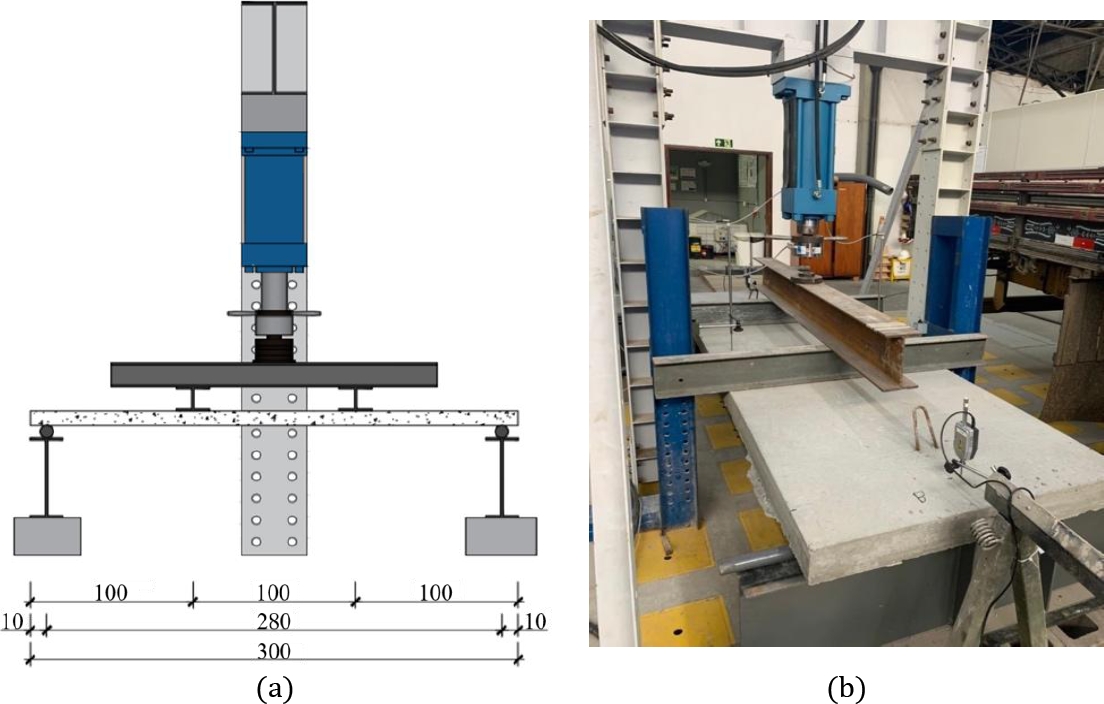
Figure 2. Flexural bending test apparatus dimensions in centimeters: (a) test body placement and instrumentation and (b) actual test under way.
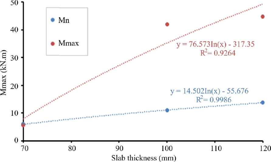
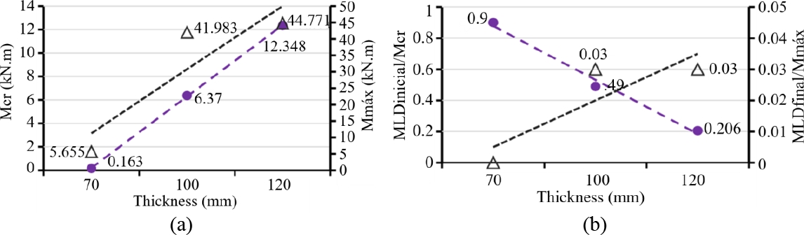
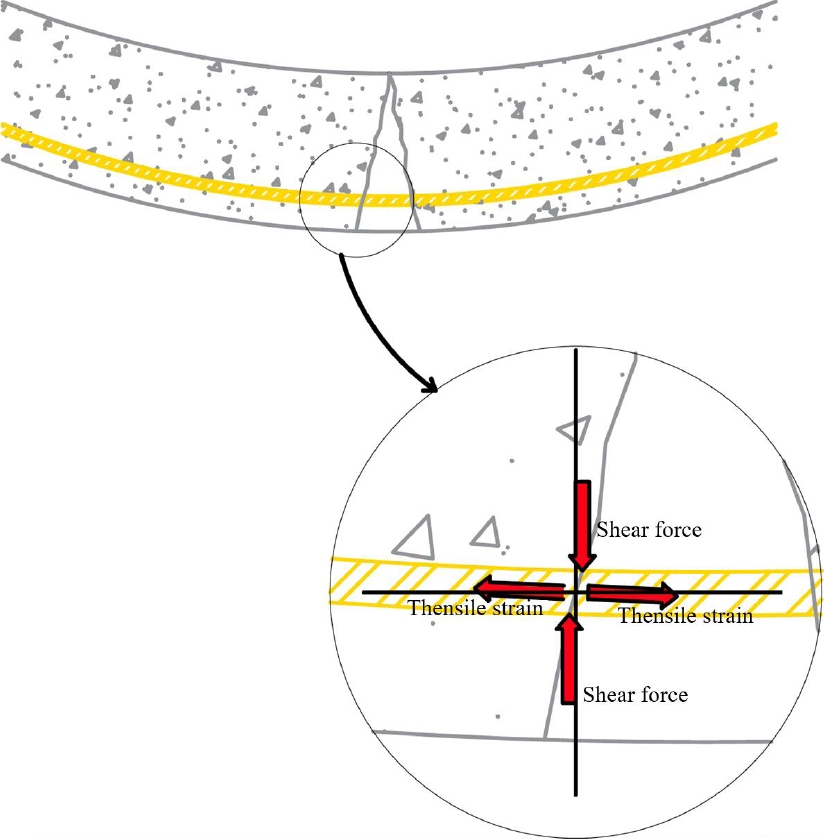
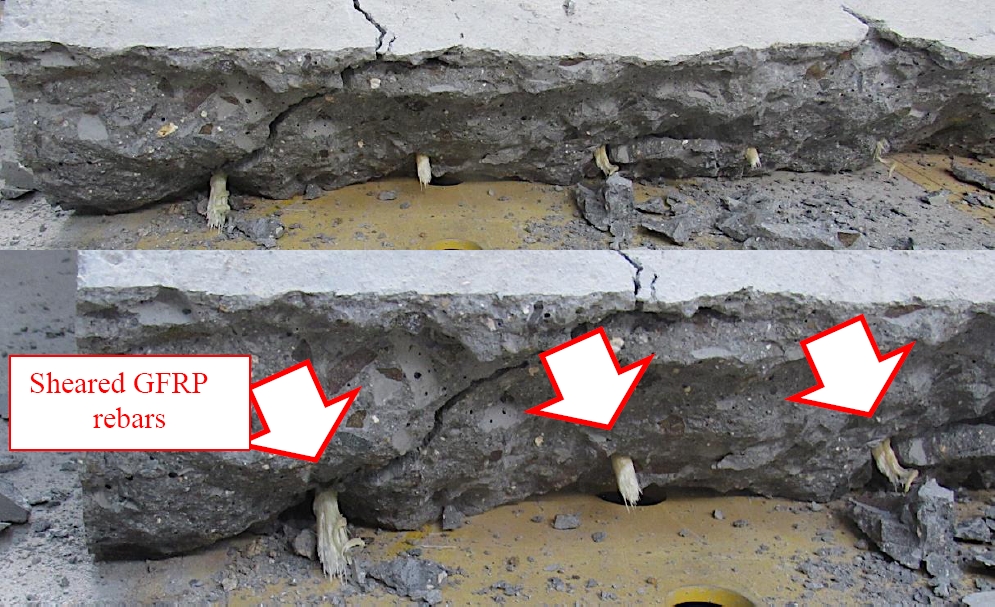
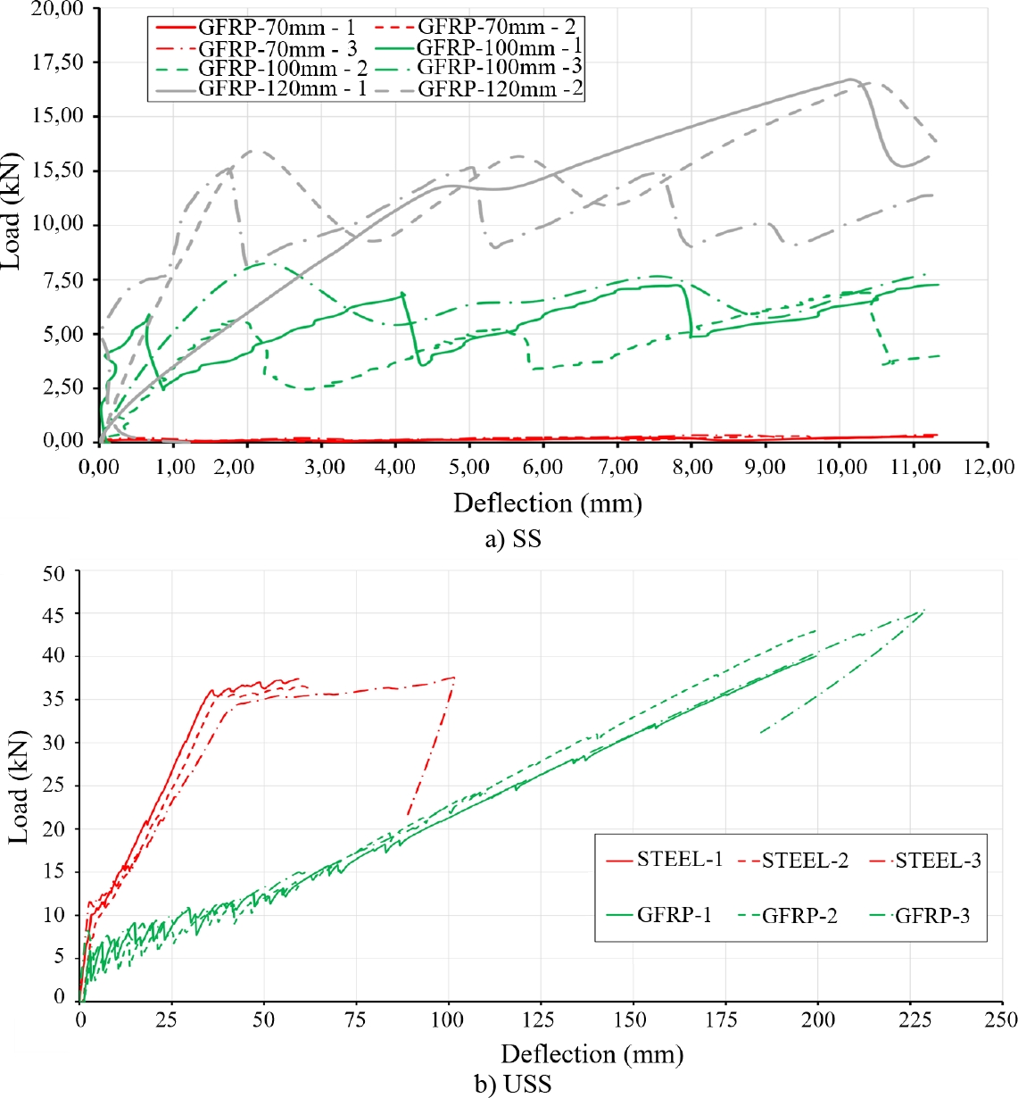
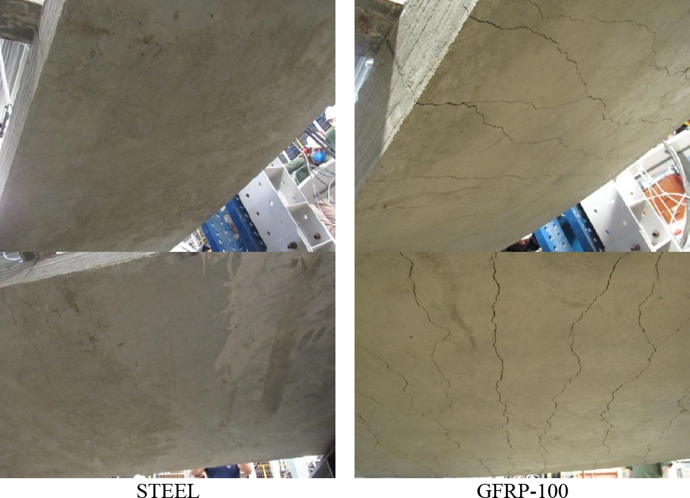
Experimental maximum loads were analyzed and compared to nominal moments calculated analytically in accordance with standard ACI 440.1R-15 (ACI 440.1R-15, 2015). The GFRP slabs were evaluated for two failure modes: (a) failure governed by concrete crushing and (b) failure governed by FRP rupture as shown in Figure 3. Figure 3. Flexural rupture conditions for FRP reinforced concrete. Source: ACI 440.1R-15 (2015). The resulting flexural rupture mode depended on the relation between reinforcement ratio and balanced reinforcement ratio. The reinforcement ratio (ρf), shown in Eq. 1, is the ratio between the effective cross-sectional area of the reinforcement with respect to the effective cross-sectional area of concrete. The balanced reinforcement ratio (ρfb), shown in Eq. 2, is the reinforcement ratio at which failure mode transition occurs. If ρf was less or equal than ρfb (ρf ≤ ρfb), rupture was controlled by stress on the FRP rebar. If ρf was 1.4 times greater or equal than ρfb (ρf ≥ 1.4 ρfb), rupture occurred from concrete crushing. But if ρf was less than ρfb and less than 1.4 ρfb (ρf < ρfb < 1.4 ρfb), rupture occurred both from concrete crushing and FRP stress. From the analysis of rupture mode with respect to reinforcement ratio, the nominal moment strength of the slabs () could be determined. In the case of concrete crushing rupture, the moment is given by Eq. 3. In the case of FRP rebar rupture, the moment is given by Eq. 4. The nominal moment of either failure modes must be multiplied by a reduction coefficient (Ø) given by Eq. 5. Calculations were done as per ACI 440.1R-15 (ACI 440.1R-15, 2015) and compared with maximum moments and deformation limit moments from experimental data. From these results, the safety coefficients of each of the tested structural slab element was evaluated. 3. RESULTS 3.1. Experimental GFRP flexural bending behavior The results from the 4-point flexural bending tests on the GRFP slabs are shown in Table 2. Table 2. Average values and standard deviation of properties measured on GFRP reinforced slabs. Table 2 shows that f1 for all slabs was lower than the displacement load of L/250 for 11.2 mm, considering the specimen size. The values of f1 and f𝞭SS also increased as slab thickness increased but at a low rate. Nonetheless, the formation of the first crack was delayed and the gain in rigidity was basically due to the slab thickness. The f1 / f𝞭SS ratio approached 1.0 as slab thickness increased: 0.66 for GFRP-70, 0.87 for GFRP-100 and 0.95 for GFRP-120. Decreased rigidity of an element was linked to premature occurrence of the first crack, as noted by Jabbad and Farid (Jabbar; Farid, 2018). Consequently, thinner slabs with less concrete present relied on the reinforcement ratio to resist concrete cracks (Ebead; Marzouk, 2004). Thus, in the case of the 70 mm GFRP slab, increases in reinforcement ratio would bring more relevant by increasing the Mcr than increasing the slab thickness. Increases in slab thickness limited deformability, which was expected from reference studies (Peled; Bentur; Yankelevsky, 1998). The GRFP-120 slabs had the least deflection, of up to 116 mm, which was less than half of the maximum span deflection measured for GRFP-70. Moments Mcr and Mmax also increased with increasing slab thickness, with a 70% increase in thickness resulting in a 7 fold increase in Mmax. As the loading decreased with respect to increase in centre line deflection (verified in a deflection curve), the instantaneous moments at load decrease (MLD) were determined. In the case of GRFP slabs, higher deformability was a consequence of the 50 GPa modulus of elasticity of the reinforcement, which made MLD more important in the first 1/3 of the loading curve due to cracking. Also noticeable in Table 2 was that the MLD,initial/Mcr ratio decreased as slab thickness increased. The value of MLD was substantial for GFRP-70 slabs, representing nearly 90% of the load for the first crack to occur. This ratio decreased to 50% for GFRP-100 and 20% for GFRP-120. Even for thicker slabs, this load decrease resulting from the further formation or propagation of cracks would be of interest, as noted by Zheng, Yu (Zheng; Yu; Pan, 2012). Thicker slabs had more control over cracking since reinforcements were closer to the edges being stressed. In the case of the thinner GRFP-70 slab, the concrete cover was 20 mm, reinforcements were closer to the center of gravity of the element rather than the edge and the thinner slab also had a smaller moment arm. These characteristics resulted in a delay in redistributing of the loads and more significant drops in stress. Figure 4 shows the data points and curve fits of cracking moment (Mcr), maximum moment (Mmax) and moments at initial and final load decreases (MLD,initial/Mcr and MLD,final/Mmax) with respect to slab thickness for all GRFP slabs. Figure 4. (a) Cracking and maximum moments and (b) MLD ratios with respect to thickness of GRFP reinforced slabs of this study. Figure 4(a) shows that Mcr increased as slab thickness increased, and the values were correlated since the curve fit had R2 = 1. The same analytical result was observed for Mmax. As for the ratios of Fig. 4(b), MLD,initial/Mcr decreased as slab thickness increased. This behavior was attributed to the increase in rigidity of the element, which was directly related to the change in inertia as thickness increased. The remained proportional between the slabs as a result of all slabs being produced with the same type of concrete with a tensile strength of approximately 3.2 MPa. On the other hand, MLD, final/Mmax remained essentially at zero for all slabs. This was representative of the lack of or negligible drop in loads at the last 1/3 of the deflection curves of Figure 5. Figure 5 also shows that, at the initial and final stages of the test, there were formation and propagation of several cracks, respectively as observed by (Ahmed et al., 2020). This was a result of reinforcement stretching across the crack and was an expected behavior also observed in the studies of (Barris et al., 2013; Erfan et al., 2021). Figure 5. Deflection curves for GFRP reinforced slabs of this study, a) Useful service life; b) Design service life. Figure 5(a) shows SS loads and their fluctuations up to a deflection of 11.2 mm. Slabs GFRP-100 and GFRP 120 presented reduction in load and high deflections, with similar behavior, characterizing the multiple cracking behavior. Slab GFRP 120 showed a reduction in both the major cracking and span deflection. Only the slabs identified as GFRP-70mm did not behave similarly, due to the propagation of a single crack. The SS loads presented several peaks indicative of early cracks before the deflection limit in the analysis was reached. This was a result of the relation between cracking load and SS deflection limit. As slab thickness increased, the curves became more similar but the number of drops in load decreased. This was in agreement with the hypothesis of increased element rigidity and delayed crack nucleation at larger thicknesses (Jabbar; Farid, 2018). The USS results of Fig. 5(b) show distinct initial and final stages for all slabs. In the case of GFRP-100 and GFRP-120, the occurrence of drops in load and number of peaks dampened once loading reached 50% of the maximum value. These behaviors were due to GFRP rebars having modulus of elasticity of similar value as the type of concrete used. Drops in load and increase in deflection were indicative of the formation of new cracks without activity from the rebars, which acted as passive reinforcement at this stage. Reinforcement became active once concrete crackd and stretched the fibers across the openings. This required higher loads to be applied to form new cracks as higher stresses were needed to open new cracks. If the load limit for new cracks were not reached, propagation of the older cracks occurred. It should be noted that rupturing occurred suddenly in the elements despite high flexibility. Figure 6 shows the stress distribution in the interface region between GFRP rebar and propagated crack. As cracks propagated, rebars rotated with respect to the crack inducing combined tensile and shearing stresses in the interface region. This occurred at the detached segment of the opening and at the end of the crack, where the rebar remained bonded to the concrete and followed the same angle of deformation as the element. The measured deflections exceeded acceptable values for concrete elements set by standards ACI 318, EN1992-1-1, ABNT NBR 6118 and others. Misalignment between the crack walls induced shearing on the GFRP rebar. This was noticeable in the visual appearance of the GFRP rebar after slab rupture shown in Fig, 7. Thus, the sudden rupture of the elements was a result of the combined stresses due to tension and shearing of the rebars. Figure 6. Stress distribution in the interface region between GFRP rebar and crack which led to shearing rupture. Figure 7. Visual appearance of GFRP rebar after rupture from internal shear caused by crack propagation in the slab 3.2. Comparison between steel and GFRP reinforced slabs The 100 mm thick slab with steel reinforcement was compared with GFRP-100 and the results shown in Table 3. Both slabs had similar performance in that they crack before the applied load reached f𝞭SS. However, as shown in Table 3, the specific values of f𝞭SS were distinct for each type of reinforcement. Steel had a higher modulus of elasticity then GFRP and, by extension, higher f𝞭SS. While this presented superior and predictable behaviors, the maximum load (fu) of the steel slab was lower and the maximum deflection (𝞭USS) was 65% lower than the value for GFRP-100. Table 3 Average values and standard deviation of properties of 100 mm thick slabs with steel or GFRP reinforcement. The modulus of elasticity of each type of reinforcement affected the deformability of the element. Steel has a modulus of elasticity 3 to 4 times higher than GFRP and, by extension; steel elements should have deformations of around 3 times smaller. However, results showed that the maximum load (fu) was lower for the steel slab due to GFRP having higher tensile strength than steel. Comparisons of the deflection curves between steel and GFRP reinforced slabs are shown in Figure 8 for SS and USS. Results are shown for each of the 3 samples of each type of slab. The drop in loads for SS, when evaluated as MLD along the curves, showed that the steel slab had variations of Mcr around 13 times smaller and Mmax around 2 times smaller than GFRP-100. This result was also attributed to the difference in modulus of elasticity between the materials. For the USS curve, the steel slab also presented an upwards gain in strength which, after stabilizing, represented the yield of the material. In contrast, the behavior of GFRP-100 presented a steady increase in load until sudden rupture. This linear behavior between stress and deformation was noted on individual rebars by Sadraie, Khaloo and Soltani (Sadraie; Khaloo; Soltani, 2019) and shown in this study to also apply to reinforced slabs. Figure 8. Deflection curves of slabs with steel reinforcement and GFRP-100, a) Useful service life; b) Design service life. The SS curve of Fig. 8 also shows drops in load of less than 1 kN for the steel slab which became more intense in the final 1/3 of the curve. In comparison, GFRP-100 presented more relevant drops in the initial 1/3 and final 1/3 of the curve. This indicated that the steel slab had better control over cracking and had more cracks with small openings, which explained the smoother drops in load. In the last 1/3 of the curve, the steel reinforcement was at the creep limit which amplified drops in load as the response time of the material was already compromised by stretching. The visual differences in cracking on the stressed face of the steel reinforced slab and GFRP-100 are shown in Figure 9. Figure 9. Crackd face of the steel reinforced slab and GFRP-100. Overall, it could be stated that the magnitude of reduction in load due to cracks and the number of peaks in the load curve were related to the modulus of elasticity of the reinforcement, while Mmax was related to the stress limit of creep of the reinforcement. Since the GFRP rebars had higher strength, GFRP-100 was able to reach higher Mmax than the steel slab even if the rebars were ruptured from shearing. 3.3 Experimental and analutical comparative analuysis Table 4 presents the maximum flexing bending moment (Mmax) obtained from experimental data and the nominal moment (Mn) calculated from Eq. 3 and Eq. 4 of standard ACI 440.1R-15 (ACI 440.1R-15, 2015). Table 4. Comparison of experimental and analytical moments for GFRP reinforced slabs. The comparative analysis of Table 4 shows that the experimental flexural bending moments for thicker slabs were higher than the analytical values. In contrast, for the thinner 70 mm slab, the analytical moment was higher than the experimental value. In terms of the Mmax/Mn ratio, it could be stated that the thicker 100 mm and 120 mm slabs had a higher margin of safety than the 70 mm slab. Figure 10 shows a graphical comparison of the experimental and analytical flexural bending moments. The analytical moment had a proportional behavior between Mmax and slab thickness, indicating that slab thickness had little effect in gains in strength. On the other hand, experimental moments showed clear gains in strength as slab thickness increased. It should be noted all slabs had the same reinforcement ratio regardless of thickness. Figure 10. Experimental and analytical flexural bending moments with respect to slab thickness The comparative analysis demonstrated an elevated margin of safety. However, the maximum applied load that resulted in the maximum flexural bending moment should not be considered an effective moment under normal operating conditions since it did not include creep effects and long-term loading. This is due to conditions of use of the structure, since if the deformation exceeds the limit, the structure is considered inoperative. On the other hand, calculated nominal moments were lower since they included creep effects and other factors in their analytical expressions. Standards ACI 318, EN1992-1-1, ABNT NBR 6118 and others defined an upper limit to specific deformations of rebars in order to prevent excessive deflection of structural elements. Also, Fakoor and Nematzadeh (Fakoor; Nematzadeh, 2021) stated that above 8% specific deformation, the structural element is no longer planar and consequently no longer compatible with Hooke’s law. Another analysis could be done considering that, for the 70 mm slab, the calculated reinforcement ratio is lower than the balanced reinforcement ratio. Consequently, the thinner slab ruptured from concrete crushing while thicker slabs ruptured from rebar stresses. Thus, for thicker slabs, the decrease in load capacity must account for the creep of the rebar material. Since GFRP rebars had a relatively low modulus of elasticity, deformation from long-term loads were lower (Gonilha; Correia; Branco, 2013; Miàs et al., 2013). The effects of short and long-term loading on beams with GFRP reinforcement were evaluated by Miàs et al. (Miàs et al., 2015). Results showed that flexing-induced cracks had openings 25% larger for beams subjected to long-term loads. 4. CONCLUSIONS The conclusions obtained in this study are: - The increase in the thickness of GFRP-reinforced slabs resulted in an effective linear increase in load capacity and a decrease in deflection, due to the greater stiffness of the element; - The deflection curves of the GFRP slabs, especially those related to the USS, reflected the same linear behavior as experiments conducted only with reinforcing bars; - The comparison between the types of reinforcement determined that the GFRP-reinforced slabs presented greater deflection than the steel-reinforced slabs. This was attributed to GFRP having a modulus of elasticity approximately 4 times lower than steel; - The load of the first crack evidenced in the steel-reinforced slab and in the GFRP-reinforced slab, both with the same thickness and number of bars, was 10.2 kN and 6.5 kN, respectively. However, if the slab thickness is increased by 2 cm, the first crack load is increased, reaching a value of 12.6 kN; - The experimental results were compared with analytical calculations of international standards. Since the experimental analysis did not include all the coefficients in the mathematical expressions, it was expected that the experimental results would be superior to the analytical calculations, and this was correctly proven in the results of this study. Showing that the technical standard used to calculate GFRP reinforced structures is too conservative, and the mitigation coefficients can be revised. 5. ACKNOWLEDGMENTS The authors are grateful for the assistance in carrying out the tests and purchasing raw materials, especially by itt Performance - UNISINOS 6. REFERÊNCIAS American Concrete Institute (2015), ACI 440.1R-15 - Guide for the Design and Construction of Structural Concrete Reinforced with Fiber-Reinforced Polymer (FRP) Bars. Farmington Hills: Reported by ACI Committee 440. ASTM International (2020), ASTM C143/20 - Standard Test Method for Slump of Hydraulic-Cement Concrete. West Conshohocken, PA. Ahmed, A., Guo, S., Zhang, Z., Shi, C., Zhu, D. (2020), A review on durability of fiber reinforced polymer (FRP) bars reinforced seawater sea sand concrete. Construction and Building Materials, v. 256, p. 119484. https://doi.org/10.1016/j.conbuildmat.2020.119484 Arczewska, P., Polak, M. A., Penlidis, A. (2021), Degradation of glass fiber reinforced polymer (GFRP) bars in concrete environment. Construction and Building Materials, v. 293, p. 123451. https://doi.org/10.1016/j.conbuildmat.2021.123451 Ashour, A. F. (2006), Flexural and shear capacities of concrete beams reinforced with GFRP bars. Construction and Building Materials, v. 20, n. 10, p. 1005-1015. https://doi.org/10.1016/j.conbuildmat.2005.06.023 Bondaletova, L. I., Bondaletov, V. G. (2013), Polymer Composite Materials, p. 11-13 (in Russian). Bakouregui, A. S., Mohamed, H. M., Yahia, A., Benmokrane, B. (2021), Explainable extreme gradient boosting tree-based prediction of load-carrying capacity of FRP-RC columns. Engineering Structures, v. 245, n. January, p. 112836. https://doi.org/10.1016/j.engstruct.2021.112836 BARRIS, C., Torres,L., Comas,J., Miàs, C. (2013), Cracking and deflections in GFRP RC beams: An experimental study. Composites Part B: Engineering, v. 55, p. 580-590. https://doi.org/10.1016/j.compositesb.2013.07.019 Chu, K., Hossain, K. M. A., Lachemi, M. (2020), Fatigue behavior of GFRP-reinforced ECC link slabs under variable stress levels and number of cycles. Engineering Structures, v. 222, n. December 2019. https://doi.org/10.1016/j.engstruct.2020.111130 Ebead, U., Marzouk, H. (2004), Fiber-reinforced polymer strengthening of two-way slabs. ACI Structural Journal, v. 101, n. 5, p. 650-659. https://doi.org/10.14359/13387 Erfan, A. M., Abd Elnaby,R. M., Aziz Badr,A., El-sayed, T. A. (2021), Flexural behavior of HSC one way slabs reinforced with basalt FRP bars. Case Studies in Construction Materials, v. 14, p. 1-17. https://doi.org/10.1016/j.cscm.2021.e00513 Fakoor, M., Nematzadeh, M. (2021), A new post-peak behavior assessment approach for effect of steel fibers on bond stress-slip relationship of concrete and steel bar after exposure to high temperatures. Construction and Building Materials, v. 278, p. 122340. https://doi.org/10.1016/j.conbuildmat.2021.122340 Gajdošová, K., Sonnenschein, R., Blaho, S., Kinčeková, S., Pecka, J. (2020), Durability of FRP Reinforcements and Long-Term Properties. Slovak Journal of Civil Engineering, v. 28, n. 2, p. 50-55. https://doi.org/10.2478/sjce-2020-0015 Gao, D., Fang, D., You, P., Chen, G., Tang, J. (2020), Flexural behavior of reinforced concrete one-way slabs strengthened via external post-tensioned FRP tendons. Engineering Structures, v. 216, p. 110718. https://doi.org/10.1016/j.engstruct.2020.110718 Gonilha, J. A., Correia, J. R., Branco, F. A. (2013), Creep response of GFRP-concrete hybrid structures: Application to a footbridge prototype. Composites Part B: Engineering, v. 53, p. 193-206. https://doi.org/10.1016/j.compositesb.2013.04.054 Gravina, R. J., Li, J., Smith, S. T., Visintin, P. (2020), Environmental Durability of FRP Bar-to-Concrete Bond: Critical Review. Journal of Composites for Construction, v. 24, n. 4, p. 03120001. https://doi.org/10.1061/(ASCE)CC.1943-5614.0001016 Jabbar, S. A. A., Farid, S. B. H. (2018), Replacement of steel rebars by GFRP rebars in the concrete structures. Karbala International Journal of Modern Science, v. 4, n. 2, p. 216-227. https://doi.org/10.1016/j.kijoms.2018.02.002 Kaszubska, M., Kotynia, R., Barros, J. A. O. (2017), Influence of Longitudinal GFRP Reinforcement Ratio on Shear Capacity of Concrete Beams without Stirrups. Procedia Engineering, v. 193, p. 361-368. https://doi.org/10.1016/j.proeng.2017.06.225 Mahroug, M. E. M., Ashour, A. F., Lam, D. (2014), Experimental response and code modelling of continuous concrete slabs reinforced with BFRP bars. Composite Structures, v. 107, p. 664-674. https://doi.org/10.1016/j.compstruct.2013.08.029 Manalo, A., Maranan, G., Benmokrane, B., Cousin, P., Alajarmeh, O., Ferdous, W., Liang, R., Hota, G. (2020), Comparative durability of GFRP composite reinforcing bars in concrete and in simulated concrete environments, Cement and Concrete Composites, Volume 109, 103564, ISSN 0958-9465, https://doi.org/10.1016/j.cemconcomp.2020.103564 Miàs, C., Torres, L., Turon, A., Sharaky, I. A. (2013), Effect of material properties on long-term deflections of GFRP reinforced concrete beams. Construction and Building Materials, v. 41, p. 99-108. https://doi.org/10.1016/j.conbuildmat.2012.11.055 Miàs, C., Torres, L., Turon, A. (2015), Short and long-term cracking behaviour of GFRP reinforced concrete beams. Composites Part B: Engineering, v. 77, p. 223-231, 2015. https://doi.org/10.1016/j.compositesb.2015.03.024 Najafabadi, E. P., Bazli, M., Ashrafi, H., Oskouei, A. V. (2018), Effect of applied stress and bar characteristics on the short-term creep behavior of FRP bars, Construction and Building Materials, Volume 171, Pages 960-968, ISSN 0950-0618, https://doi.org/10.1016/j.conbuildmat.2018.03.204 Noël, M., Soudki, K. (2014), Estimation of the crack width and deformation of FRP-reinforced concrete flexural members with and without transverse shear reinforcement. Engineering Structures, v. 59, p. 393-398. https://doi.org/10.1016/j.engstruct.2013.11.005 Peled, A., Bentur, A., Yankelevsky, D. Z. (1998), The nature of bonding between monofilament polyethylene yarns and cement matrices. Cement and Concrete Composites, v. 20, n. 4, p. 319-327. https://doi.org/10.1016/S0958-9465(98)00007-9 Rosa, I. C., Santos,P., Firmo,J. P., Correia, J. R. (2020), Fire behaviour of concrete slab strips reinforced with sand-coated GFRP bars. Composite Structures, v. 244, n. December 2019, p. 112270. https://doi.org/10.1016/j.compstruct.2020.112270 Sadraie, H., Khaloo, A., Soltani, H. (2019), Dynamic performance of concrete slabs reinforced with steel and GFRP bars under impact loading. Engineering Structures, v. 191, n. December 2018, p. 62-81. https://doi.org/10.1016/j.engstruct.2019.04.038 Satasivam, S., Bai, Y., Yang, Y., Zhu, L., Zhao, X.-L. (2018), Mechanical performance of two-way modular FRP sandwich slabs. Composite Structures, v. 184, n. September 2017, p. 904-916, https://doi.org/10.1016/j.compstruct.2017.10.026 Shi, J., Wang, X., Wu, Z., Zhu, Z. (2015), Creep behavior enhancement of a basalt fiber-reinforced polymer tendon. Construction and Building Materials, v. 94, p. 750-757, https://doi.org/10.1016/j.conbuildmat.2015.07.118 Shi, X., Park, P., Rew, Y., Huang, K., Sim, C. (2020), Constitutive behaviors of steel fiber reinforced concrete under uniaxial compression and tension, Construction and Building Materials, Volume 233, 117316, ISSN 0950-0618, https://doi.org/10.1016/j.conbuildmat.2019.117316 Starkova, O., Buschhorn, S. T., Mannov, E., Schulte, K., Aniskevich, A. (2012), Creep and recovery of epoxy/MWCNT nanocomposites, Composites Part A: Applied Science and Manufacturing, Volume 43, Issue 8, Pages 1212-1218, ISSN 1359-835X, https://doi.org/10.1016/j.compositesa.2012.03.015. Wang, X., Shi, J., Liu, J., Yang, L., Wu, Z. (2014), Creep behavior of basalt fiber reinforced polymer tendons for prestressing application. Materials and Design, v. 59, p. 558-564, https://doi.org/10.1016/j.matdes.2014.03.009 Zhang, P., Hu, R., Zou, X., Liu, Y., Li, Q., Wu, G., Sheikh, S. A. (2021), Experimental study of a novel continuous FRP-UHPC hybrid beam, Composite Structures, Volume 261, 113329, ISSN 0263-8223, https://doi.org/10.1016/j.compstruct.2020.113329. Zheng, Y., Yu, G., Pan, Y. (2012), Investigation of ultimate strengths of concrete bridge deck slabs reinforced with GFRP bars. Construction and Building Materials, v. 28, n. 1, p. 482-492. https://doi.org/10.1016/j.conbuildmat.2011.09.002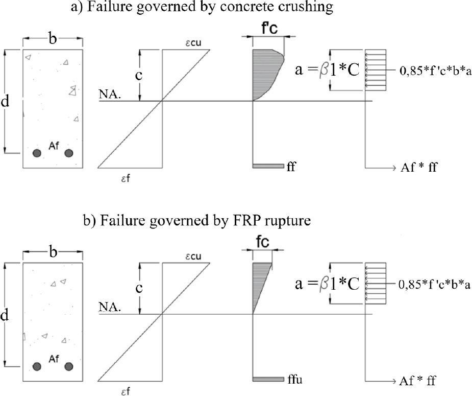
Eq. 1
Eq. 2
Eq. 3
Eq. 4
Eq. 5
Property
Slabs
GRFP-70 (70 mm)
GRFP-100 (100 mm)
GRFP-120 (120 mm)
f1 (kN)
0.2 ± 0.01
6.5 ± 0.99
12.6 ± 0.80
𝞭1 (mm)
0.2 ± 0.05
3.8 ± 0.54
7.1 ± 0.86
f𝞭SS (kN)
0.3 ± 0.03
7.5 ± 0.54
13.3 ± 0.60
fu (kN)
5.8 ± 0.27
42.8 ± 2.20
45.7 ± 0.11
𝞭SS (mm)
255 ± 180
209 ± 139
116 ± 040
Mcr (kN.m)
0.2 ± 0.01
6.4 ± 0.97
12.3 ± 0.78
Mmax (kN.m)
5.7 ± 0.27
42.0 ± 2.16
44.8 ± 0.11
MLD,initial/Mcr
0.9 ± 0.00
0.5 ± 0.00
0.2 ± 0.00
MLD,final/Mmax
0.0 ± 0.00
0.0 ± 0.00
0.0 ± 0.00
f1 – maximum load at first crack; 𝞭1 – deflection at first crack; f𝞭SS: – maximum load for SS; fu – maximum load ; 𝞭SS – maximum deflection for SS; Mcr – moment at first crack; Mmax – maximum moment, MLD,initial – moment at initial load decrease, MLD,final – moment at final load decrease

Property
Slab with h=100 mm
Steel
GFRP-100
f1 (kN)
10.2 ± 1.02
6.5 ± 0.99
𝞭1 (mm)
2.41 ± 0.04
3.8 ± 0.54
f𝞭SS (kN)
15.0 ± 0.60
7.5 ± 0.54
fu (kN)
37.2 ± 0.43
42.8 ± 2.20
𝞭USS (mm)
7.4 ± 1.93
20.9 ± 1.39
Mcr (kN.m)
10.0 ± 1.00
6.4 ± 0.97
Mmax (kN.m)
36.5 ± 0.42
42.0 ± 2.16
MLD,initial/Mcr
0.0 ± 0.00
0.5 ± 0.00
MLD,final/Mmax
0.0 ± 0.00
0.0 ± 0.00
Moments
Slab thickness
70 mm
100 mm
120 mm
Mmax (kN.m)
5.7
42
44.8
Mn (kN.m)
5.99
10.94
13.86
0.95
3.84
3.23