![]()
| Basic Research | https://doi.org/10.21041/ra.v15i2.739 |
Pathological manifestations in a prestressed concrete flat slab building - a case study: part II - structure reinforcement
Manifestaciones patológicas en una edificación con losas pretensadas - un estudio de caso: parte II - reforzamiento estructural
Manifestações patológicas em uma edificação com lajes protendidas – um estudo de caso: parte II – reforço da estrutura
A. B. S. Santos Neto1*, A. Lübeck2, P. J. Sarkis3, J. M. Sarkis3
1 Programa de Pós-Graduação em Arquitetura, Urbanismo e Paisagismo, Universidade Federal de Santa Maria, Brasil. 2 Programa de Pós-Graduação em Engenharia Civil, Universidade Federal de Santa Maria, Brasil. 3 Sarkis Engenharia Estrutural, Santa Maria, Rio Grande do Sul, Brasil. *Contact author: almir.neto@ufsm.br Received: 15/05/2024 Abstract
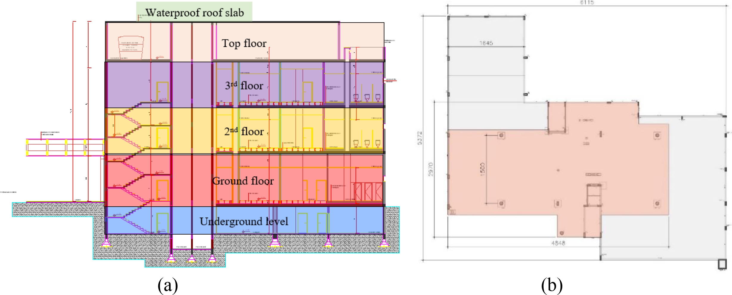
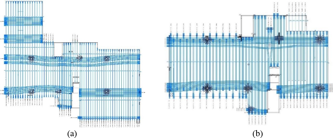
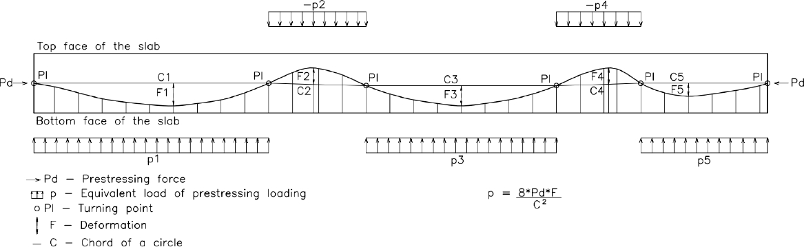
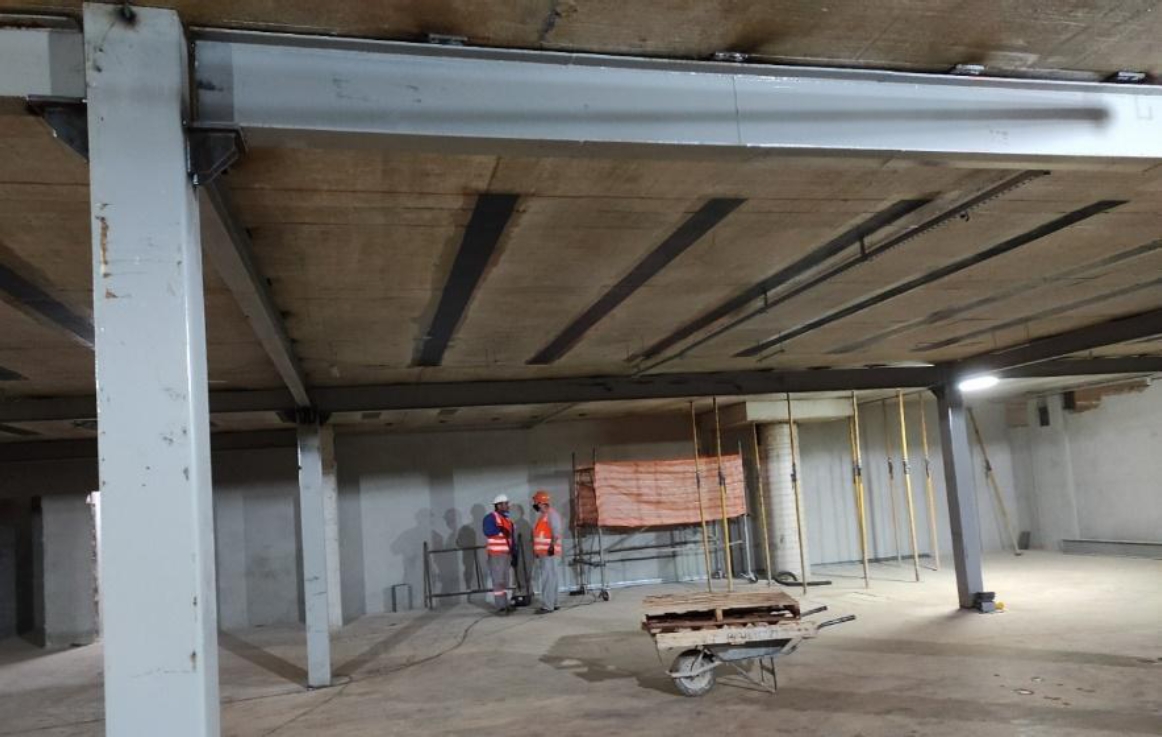
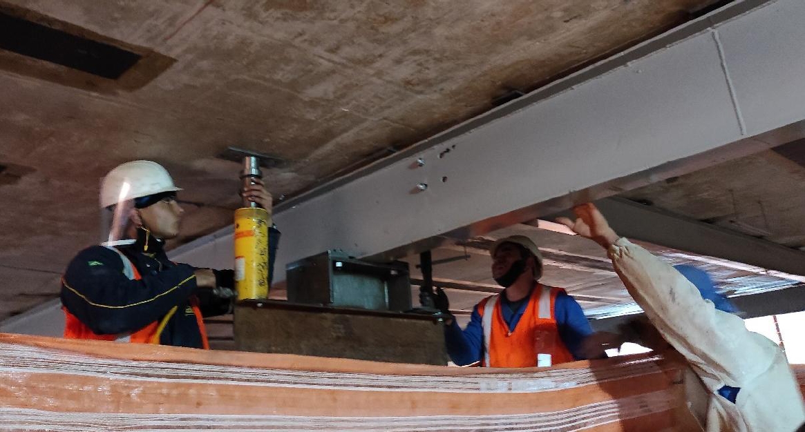
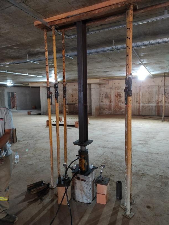
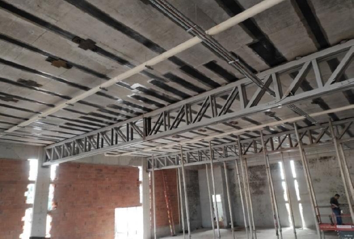
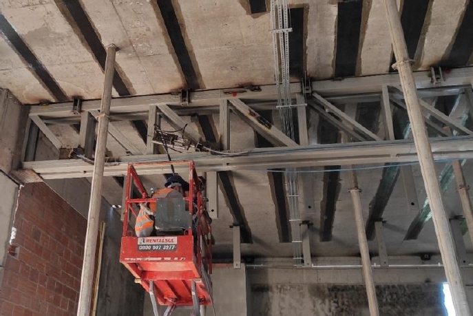
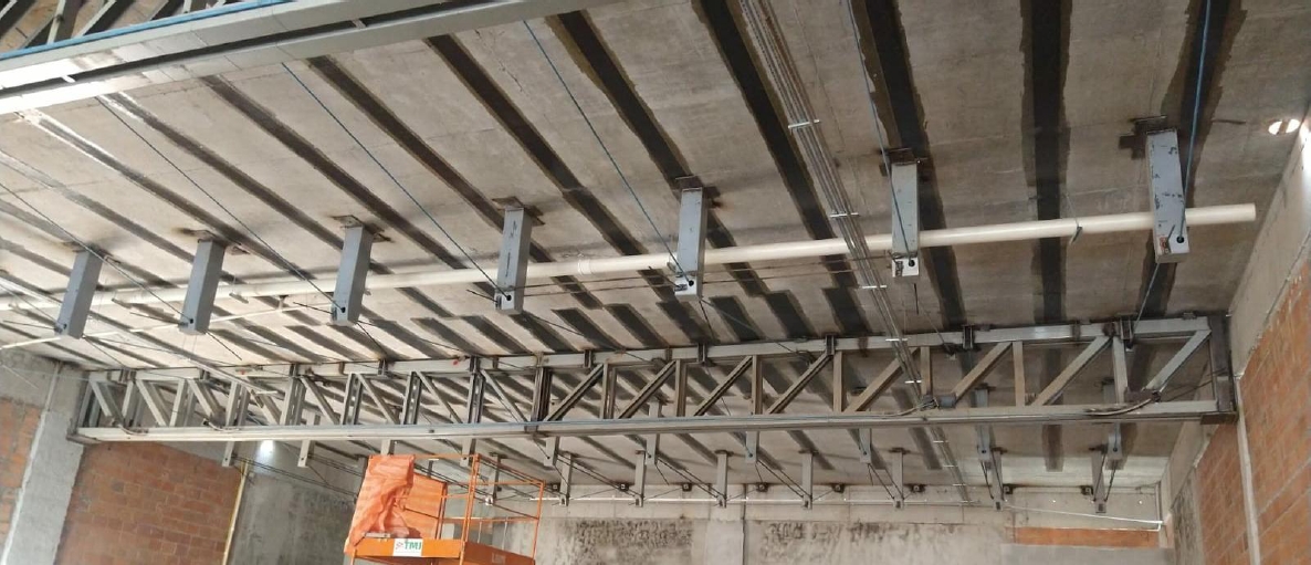
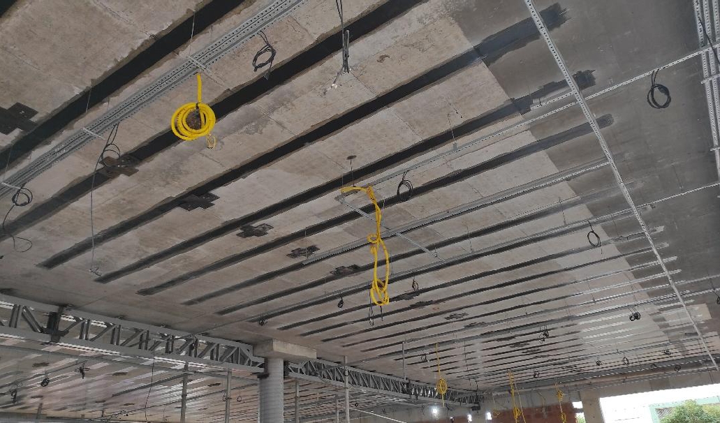
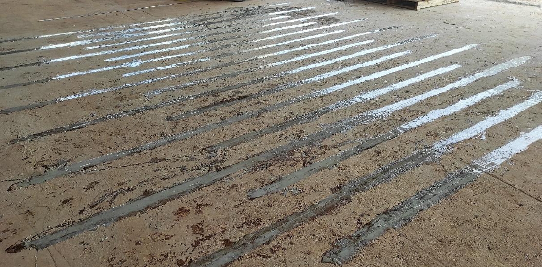
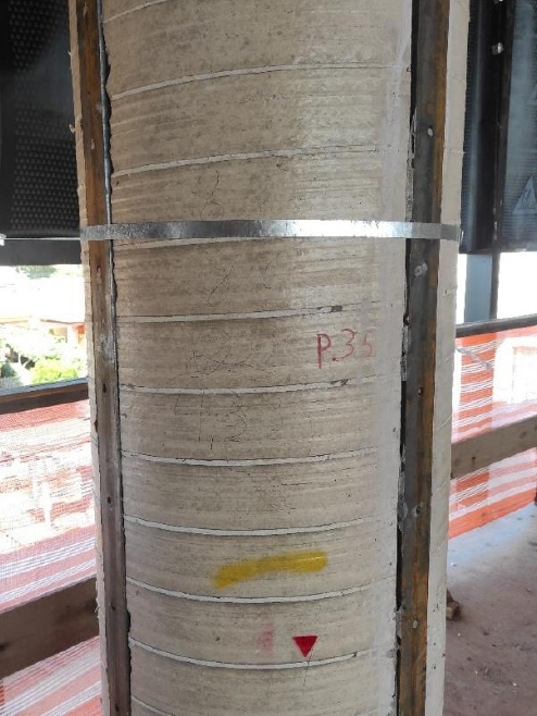
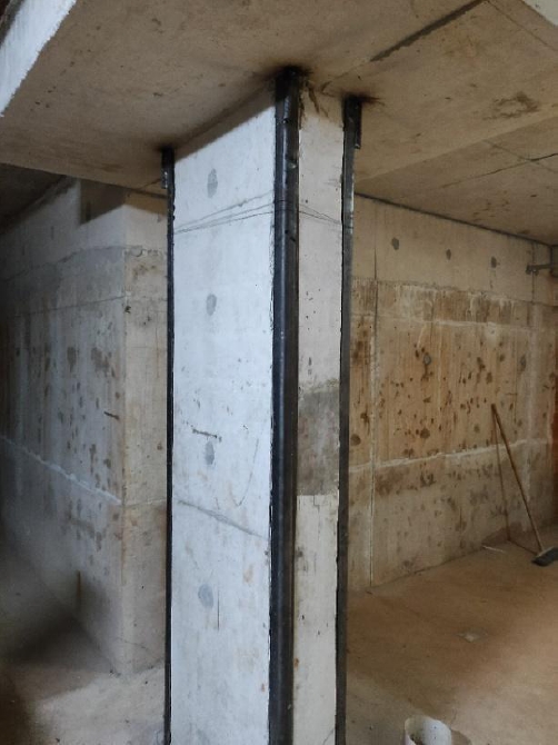
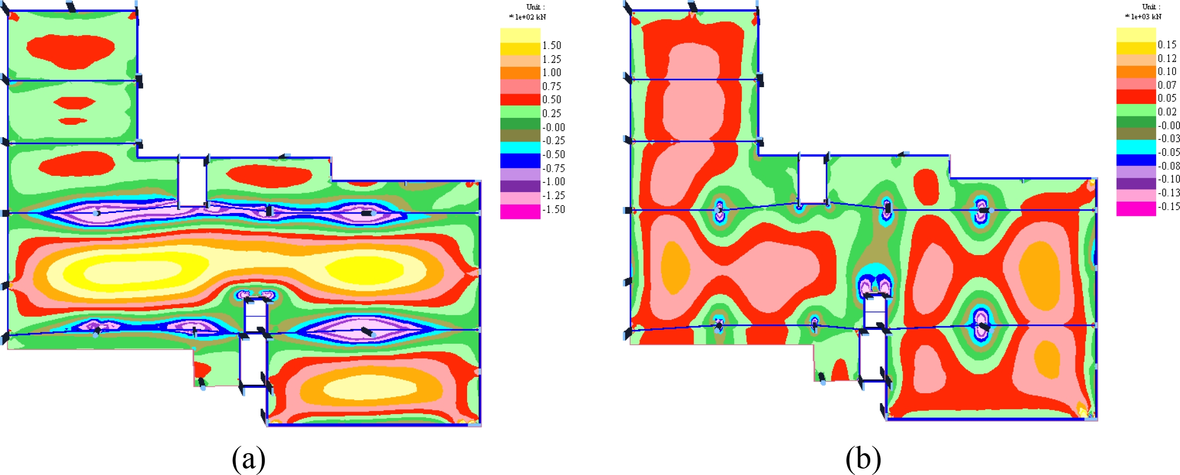
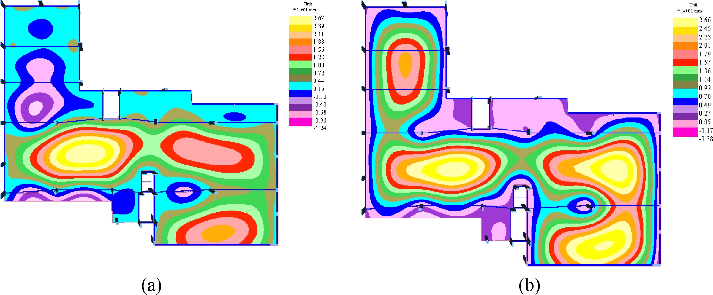
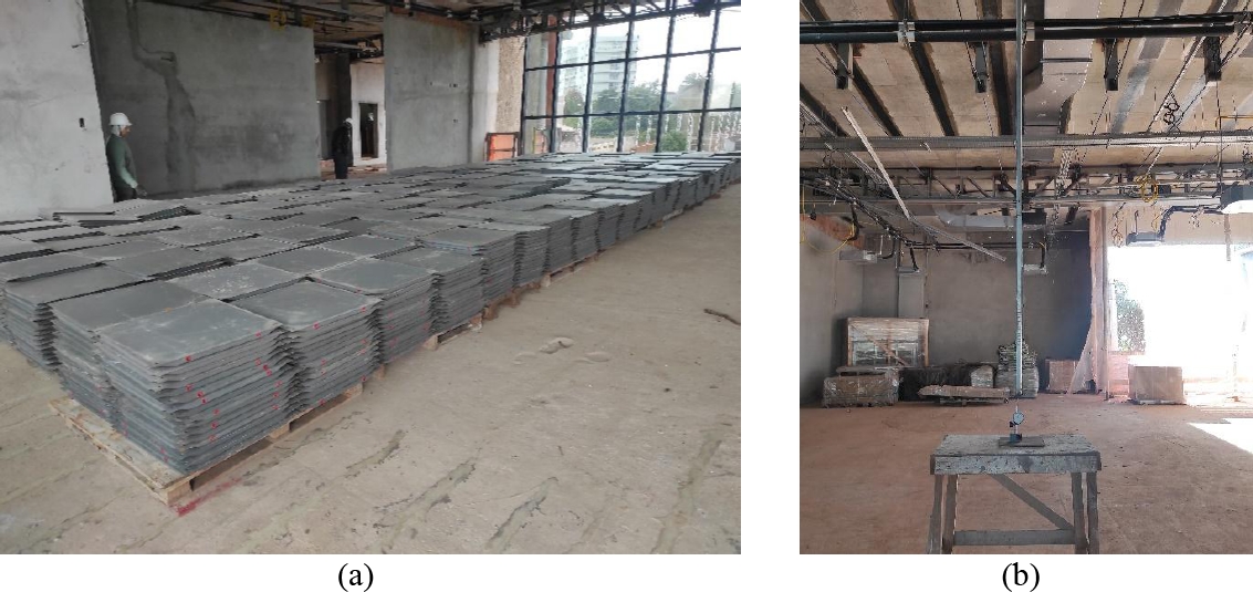
Prestressed concrete flat slabs with unbonded tendons are widely used in Brazil due to their advantages. However, the bold achieved with prestressed structures often results in projects with greater intricacy. This paper presents a case study of a commercial building constructed in Rio Grande do Sul, designed with prestressed concrete flat slabs with unbonded tendons. Some pathological manifestations, such as excessive deflections and cracks in the slabs, were observed during the construction phase. The description of the structural reinforcement solutions used in the slabs is presented, including bonded overlays, carbon fiber tape inserts, and externally prestressed metallic reinforcements. At the end of the reinforcement works, load tests were conducted on the slabs, demonstrating the efficiency of the used solutions. Keywords: prestressed concrete flat slab; prestressed concrete; pathological manifestations in constructions. 1. INTRODUCTION This study presents the recovery and structural reinforcement work conducted on a commercial building and is complementary to the study “Pathological Manifestations in a Prestressed Concrete Flat Slab Building - A Case Study: Part I - Structural Analysis.” The commercial building was composed of a partially underground level (providing parking spaces, storage, changing rooms, water basin and depository), ground floor (providing public access, reception, auditorium, commercial spaces, restrooms, pantry etc.), 2nd and 3rd floor offices (holding office spaces, meeting rooms, training rooms, coffee break lounge, kitchen, restrooms and an external area split between a green roof area and a restricted access area), top floor with no public access (containing the roof slab and rooftop water reservoir) and an additional waterproof roof slab covering the reservoir. Thus, the building contained 6 levels (slabs) and a total area of 5,697.00 m2. Figure 1(a) shows a schematic side view cross-section of the building identifying each floor while Figure 1(b) presents an overlay of the 2nd floor (grey) and 3rd floor (orange) floorplans. On the plane of Figure 1(b), the 2nd floor has a horizontal length of 61.15 m and a vertical height of 53.72 m while the 3rd floor has reduced dimensions of 48.48 m by 29.7 m. The structure was constructed with no expansion or isolation joints. Figure 1. (a) Schematic cross view of the building and floors; (b) overlay of 2nd floor (grey) and 3rd floor (orange) floor plans (in cm). A survey of the building and a technical analysis of the original structural project were conducted and its results presented in the study “Pathological Manifestations in a Prestressed Concrete Flat Slab Building - A Case Study: Part I - Structural Analysis.” Part I ascertained that the slab thickness used in construction was thinner than recommended in reference works and standards. In addition, a different type of slab could have been used such as a prestressed joist slab which would have significantly decreased the slab weight and allowed a thicker element to be used. As a caveat, it was noted that reference works indicated thinner slabs could be used if properly checked with respect to maximum deflection arrow, normal stress limits and risk of excessive vibrations. The technical analysis also determined that, in some regions of the slab, normal stresses exceeded the serviceability limit state of fissuring (SLS-F) as recommended by standard NBR 6118 (ABNT, 2014). This produced visible fissures on both top and bottom surfaces of the slabs. Positive reinforcements proposed in the structural project were also deemed insufficient on several different slabs. The analysis was also unable to determine an applicable negative reinforcement configuration due to the thinness of the slab as designed and constructed. Results of the technical analysis were used to elaborate a reinforcement project for the structure. The reinforcement project made use of several different techniques such as carbon fiber overlays bonded to the slabs, cut in carbon fiber tape inserts, external prestressed reinforcement with unbounded tendons and prestressed steel reinforced concrete trusses. In this case, the trusses and external reinforcements were used to partially correct slab deflection. After execution, new load tests were applied to the structure to evaluate structural performance and validate the results of the reinforcement project. This study, designated as Part II of the case study, presents a detailed description of the reinforcement techniques and the structural evaluation post execution from load tests applied to the structure 2. CASE STUDY This study was separated into sections containing a brief description of the original structural project, detailed proposal of the reinforcement project, execution of the reinforcement project and load tests applied to the structure to confirm reinforcement performance. 2.1 Original Structural Project The original structural system of the building could be described as flat prestressed slabs with edge beams and some internal columns with capitals. Beams were mostly of reinforced concrete and a single prestressed concrete one, while prestressed slabs were used on all floors except for a reinforced concrete slab covering the water reservoir at the top of the building. The prestressed slabs were 25 cm thick on all floors while the water reservoir cover slab was 15 cm thick. The entire structure was constructed from C35 class concrete (fck = 35 MPa). Unsupported gaps were around 15 m with the widest span of 16.45 m on the slab covering the roof of the auditorium (which corresponded to the 2nd floor slab). The prestressed slabs contained unbounded tendons 12.7 mm in diameter made from CP 190 RB steel while reinforcements were made from CA-50 and CA-60 class steel. Unbonded tendons were more concentrated in one direction and more sparsely distributed in the orthogonal as shown in Figure 2(a) for the 2nd floor. A similar distribution to the 2nd floor was also used in the ground floor slab. In comparison, Figure 2(b) shows the tendon distribution on the 3rd floor which was similar to the distribution used on the top floor. Figure 2. Unbonded tendon distribution: (a) 2nd floor and (b) 3rd floor slabs. 2.2 Proposed Structural Reinforcement Project The proposed structural reinforcement project was developed with a finite element method with 1-D elements in MIX-TQS (TQS, 2011) and CAD TQS (TQS, 2018) commercial software. Prestressed tendons, both in the original and reinforcement projects, were considered to be external loads. The external load applied to the structure was determined in accordance with standard NBR 6120 (ABNT, 2019). The unbounded tendons were divided into segments comprising of the length between inflection points. Each segment was then subjected to an equivalent structural load calculated in proportion to its length (chord) and distance from the central deflection point (arrow) as shown in Figure 3 (Sarkis et al., 2023). The prestress force was simplified to already account for all losses to a final value of 12 tf (120 kN) per cable. Figure 3. Cable elements and loads in the finite element simulation Source: adapted from Sarkis et al. (2023) Trusses and metallic beam reinforcements were incorporated in the model by adding homogenized properties from the physical composite steel-concrete element to equivalent 1-D elements of the simulated slab. This process was iterative: changes in the rigidity of the 1-D elements would also change the stresses on these elements, which in turn would spur changes to the cross-sections of the elements and alter the rigidity once more. In contrast, metallic column reinforcements were added directly to the model with their individual properties. The simulation and structural analysis were done in stages. First, the structural model was constructed with prestressed cables simulated with equivalent loads. This was used to duplicate the real behavior and stresses in the structure. Second, the trusses, metallic beams and column reinforcements were added to the model with the iterative process of adjusting 1-D element rigidity until stresses in the elements were nearly unchanged. Third, external prestressed tendons with deviators with upwards effect were added to the bottom of the slab by adding upward vertical loads directly to the numerical mesh. The number of reinforcement elements and cables was determined by bringing calculated deflection arrows to levels acceptable by standards. During this stage, stresses in the reinforcements themselves were also evaluated and their dimensions adjusted as needed. Finally, once metallic reinforcement elements and external prestressed cables were inserted in the model, stresses on slabs, beam and columns were evaluated by matching internal and external loads. When external stresses exceeded the internal stresses carried by the original reinforcement, supplementary reinforcements were calculated in the form of carbon fiber elements. These simulations were conducted on Adapt Floor Pro 2018 commercial software 2.3 Reinforcement with Metallic Structure in the Ground Floor Slab The partially underground level covered by the ground floor slab was defined as parking garage. As such, it had a lower floor-to-ceiling height which impeded the installation of trusses or external prestressed reinforcement. Consequently, the reinforcement project made use of additional columns with pressed concrete piling foundations. Both original and new columns were attached to I-beams connected to plates anchored to the slab in order to achieve the performance of a composite structure. This composite structure was projected for the existing structural load in accordance with standard NBR 8800 (ABNT, 2008) and the method presented by Sarkis (2001). Figure 4 shows the additional columns and I-beams on the underground level. Also visible at the bottom of the ground floor slab are bonded carbon fiber tape segments used to supplement the lack of passive reinforcement in the slab. Figure 4. Metallic column and I-beam reinforcements in the underground level. The I-beams were loaded in place by jacking against the slab and making use of its own flexibility. Steel shims in the form of plates or sheets were placed in the span between the deformed beam and the anchored plates. Once relieved from jacking, the beams returned to their original shape and were able to carry part of the load of the slab. Figure 5 shows a jacking procedure being conducted on an I-beam. Figure 5. Workers jacking an I-beam for insertion of metallic shims. The concrete pressed pilings were installed by first digging holes in the underground floor with portable equipment due to the restriction presented by the low floor-to-ceiling height. Once the excavation depth reached the allowed extent of the equipment, pilings were driven in the holes with a hydraulic ram until the necessary strength for a driven pile foundation was reached in accordance with standard NBR 6122 (ABNT, 2019). In this process, poured concrete was used to fix the pilings in place. Figure 6 shows a hydraulic ram being used to drive the pilings into the ground. Figure 6. Hydraulic ram driving pilings into the foundation. 2.4 External Prestressed Reinforcement in Remaining Slabs 2.4.1 Prestressed Metallic Trusses In upper floors, the original architecture project specified a dropped ceiling with a height gap between 90 cm and 110 cm for utility ducts. This gap allowed the installation of steel trusses following the orientation and position of the unbounded tendons of the original structural project. A traditional truss able to reinforce the unsupported gaps and sustain current loads was limited by the height gap of the dropped ceiling and was consequently technically and financially not viable. The proposed solution was to solder and anchor the top chord of the truss directly to the slab. This created a composite truss with the slab itself acting as a compressed chord. Figure 7 shows a steel truss reinforcement anchored against the auditorium ceiling (which was also the 2nd floor slab) creating a composite slab. Figure 7. Metallic trusses anchored on the auditorium ceiling (2nd floor slab). Trusses were installed with the same procedure as the I-beams of the underground floor: jacking against the slab for mounting so that once the jacks were removed, the truss returned to its original shape and carried part of the load of the slab. Along the lower chord of the truss, tensile stresses were mitigated with horizontal prestressing cables along the bottom surface. Some trusses had a further inclined prestressed cable running through its center. Figure 8 shows the installation of a horizontal cable on the lower chord of a truss. Figure 8. Jacking of horizontal prestressed cable on the truss. 2.4.2 External Prestressed Reinforcement with Deviators External prestressing was applied perpendicularly to the steel trusses. This prestressing consisted of cables passively anchored to the slab near the top chord of the truss and actively anchored on deviators installed in the unsupported spam in order to facilitate jacking. The distance between external prestressed cables was determined iteratively by simulating their presence as external loads at their locations until edge stresses of the 1-D element models were within limits set by standards. Figure 9 shows installed external prestressed cables on the roof of the auditorium (2nd floor slab). Figure 9. External presstressed cables installed on the roof of the auditorium (2nd floor slab). 2.5 Carbon Fiber Overlay Reinforcement The original structural project contained a Q196 passive positive reinforcement in the lower face of the slab. This consisted of a square mesh with bars 5 mm in diameter spaced 10 mm apart for a total steel area of 1.96 cm²/m, which was less than the minimum required for a slab 25 cm thick. In order to supplement strength in regions with less than the minimal steel area, carbon fiber overlays were applied along the same direction as the tendons. These were applied on the lower face of all slabs of all floors of the structure. Note that in the perpendicular direction to the tendons, the original passive reinforcement was sufficient since the applicable version of standard NBR 6118 (ABNT, 2014) at the time allowed minimum reinforcement to be halved in the secondary direction of a slab. Figure 10 shows carbon fiber strips applied at the bottom of the 2nd floor slab. Figure 10. Carbon fiber strips installed at the bottom of the 2nd floor slab. 2.6 Carbon Fiber Tape Insert Reinforcement The analysis identified regions with the occurrence of negative bending moments on the top face of some slabs especially above the locations of the steel truss reinforcements. Consequently, negative reinforcements were required and were applied in the form of cut in carbon fiber tape inserts as shown in Figure 11. These were applied to the slabs on the 2nd, 3rd and 4th floor slabs. Figure 11. Sample application of cut in carbon fiber tape insert on the top of a slab. 2.7 Concrete Column Reinforcement Structural analysis also identified the need for reinforcement on some columns. Two types of reinforcements were used depending on the geometry of the column. Round columns were reinforced with T-shaped metallic profiles inserted into the column lengthwise and bonded to the concrete with structural epoxy as shown in Figure 12. Rectangular columns in the underground level were reinforced with bands of carbon fiber overlay bounded around the perimeter and L-shaped metallic profiles bonded lengthwise at the corners as shown in Figures 13 and 14. Figure 12. Round column reinforcement with metallic profiles. Figure 13. Rectangular column reinforcement with metallic profiles bonded at the corners Figure 14. Carbon fiber overlays reinforcement bounded around a rectangular column. 2.7 Structural Analysis of Metallic Reinforcements Prior to fabrication and installation, the trusses and external prestressed cables with deviators were analyzed numerically on Adapt Floor 2018 commercial software. These were placed in the simulation and subjected to new loads in accordance with the structural reinforcement project. In the reinforcement structural model, the following were considered: a) The reinforcement metallic trusses were modeled in the simulation as concrete beams with equivalent rigidity. b) Loads produced from the steel trusses and prestressed cables with deviators were modeled as local loads at specific points of the slab in the opposite direction (upwards). c) The weights of the simulated concrete beams were disregarded in the analysis. The beams themselves were modeled with their extremities freely rotating around to the major axis of inertia of the cross-section. The extremities were also freely rotating with respect to the longitudinal axis of the beams so that the overall effect was to allow the slab to deform without restrictions. d) The combination of loads of the analysis was in accordance with standard NBR 6118 (ABNT, 2014): - Loads (ULS): 1.4×DL + 1.4×VL + 1.0×HL + 1.0×RL - Elastic arrows (quasi-permanent ULS): 1.0×DL + 1.0×PL + 0.4×VL + 1.0×RL e) Another two load combinations were also used to check displacements: - Elastic arrows (RL + DL slab): 1.0×DL + 1.0×RL - Elastic arrows (RL + DL slab + PL): 1.0×DL + 1.0×RL + 1.0×RL where: DL = dead loads, VL = variable loads, HL = hyperstatic loads, RL = reinforcement loads and PL = prestressed loads Sample simulation results for the 2nd floor slab are shown in Figures 15 and 16. Figure 15 shows isocontours of bending moments in the y-direction with respect to the orientation of the figure (as in Mxx, the bending moment around the x-axis in the y-direction) and bending moments in the x-direction with respect to the orientation of the figure (as in Myy). Figure 16 shows isocontours of vertical displacements of the slab in mm for different load combinations. Figure 15. Isocontours of bending moments on the 2nd floor slab (×102 kN.m/m) (a) in the y-direction (Mxx) and (b) x-direction (Myy) with respect to the orientation of the figure. Figure 16. Vertical displacements (×101 mm) for (a) quasi-permanent load combination (instantaneous arrow) and (b) dead loads + external prestressing loads (instantaneous arrow) Results showed that metallic reinforcements and external prestressing reduced significantly slab bending moments and decreased vertical displacements (arrows) to values within tolerances recommended by standard NBR 6118 (ABNT, 2014). 2.8 Load Tests After execution of the structural reinforcement project, structural behavior was observed to be similar to the results from the simulations. Nonetheless, load tests were performed in order to ensure the safety of the reinforced structure. In total, 17 load tests were performed on different floors in accordance with procedures of standard NBR 9607 (ABNT, 2019) as shown in Figure 17. Figure 17. (a) load test on the 2nd floor slab with floor tiles and (b) equipment for measurement of deflection arrow at a point defined in the structural model. The area of the slab to be loaded and the applied load varied with each slab and were calculated to be equivalent to the ultimate limit state (ULS). A sample load plan is shown in Figure 18 for the 3rd floor slab, noting that the 2 loads were not applied simultaneously. Figure 18. Load plans for 3rd floor slab. The load test procedure consisted of first installing deformation measuring equipment with the slab unloaded. The slab was then loaded in increments of 25 % of the total planned load with deformations being measured continuously until stabilization at each step. Once fully loaded (0 h), the slab was kept in this state for 60 h with deformation measurements being conducted at 0 h, 24 h, 48 h and 60 h. The slab was then unloaded in the same order with deformations measured at 50 % total load and fully unloaded. Residual deformations were measured 4 h after fully unloaded. Deformations were measured at the center of the loaded area and at one of the longer edges so that slab deformation was calculated from the difference between measurements. Table 1 presents sample results from load test 1 (LT1) on the 3rd floor slab. Table 1. Load test 1 results on 3rd floor slab. Results from the load tests on the ground floor with new column and composite beam reinforcements were very favorable. Deformations were measured to be around 20 % of the calculations, well below predictions and limits set by standards. On floors with steel reinforcement and external prestressed cables, deflection arrows were measured to be 30 % of predicted values. In the top cover slab of the water reservoir, which was reinforced only with carbon fiber overlays and no metallic or external prestressed cables, deformations were measured to be 90 % of predicted values. It should be stressed that these deflection arrows were only from the load tests and were not cumulative with pre-existing arrows in the slabs. Total deflection arrows were not possible to determine due to some structural elements deforming from exposure to indirect sunlight, especially the larger slabs on the 2nd floor and roof cover slab. In these elements, deformations varied a few cm along the day due to solar irradiation. This further confirmed that these elements originally did not have the necessary rigidity for the intended structure. Similarly, the reinforcement project did not seek to eliminate pre-existing deflection arrows but bring them to the acceptable limits of standard NBR 6118 (ABNT, 2014). Splitting each large, continuous floor slab into smaller segments was for ease of analysis and nomenclature. The analysis showed that, in a single continuous slab, decreases in deformation at some locations would sometimes produce increases elsewhere, which made the elaboration of the reinforcement project a complex and iterative process. 3. FINAL CONSIDERATIONS After implementation of the reinforcement project, the main aspects and spaces of the architectural project were preserved. The reinforced structure was evaluated numerically and with a live load test. Results showed that the reinforcements produced the necessary structural performance. The building has been completed and currently in use with no issues reported. Nonetheless, periodic inspections are being conducted to verify the structural state. The recovery of the structure was only possible due to a combination of different reinforcement techniques coupled with analysis from established numerical models 4. REFERENCES Associação Brasileira de Normas Técnicas. (2019). NBR 6120: Ações para o cálculo de estruturas de edificações. Rio de Janeiro. Associação Brasileira de Normas Técnica. (1980). NBR 6120: Cargas para o cálculo de estruturas de edificações. Rio de Janeiro. Associação Brasileira de Normas Técnicas. (2014). NBR 6118: Projeto de Estruturas de Concreto – Procedimento. Rio de Janeiro. Associação Brasileira de Normas Técnica. (2019). NBR 6122: Projeto e Execução de Fundações. Rio de Janeiro. Associação Brasileira de Normas Técnica. (2008). NBR 8800: Projeto e Execução de Estruturas de Aço e Estruturas Mistas Aço-Concreto de Edifícios. Rio de Janeiro. Associação Brasileira de Normas Técnica. (2019). NBR 9607: Prova de Carga Estática em Estruturas de Concreto – Requisitos e Procedimentos. Rio de Janeiro. Associação Brasileira de Normas Técnicas. (2023). NBR 6118: Projeto de Estruturas de Concreto. Rio de Janeiro. Sarkis, J. M. (2001), “Vigas Reforçadas sob Carregamento: Um Método para Simulação Matemática”. Dissertação de Mestrado. Programa de Pós-Graduação em Engenharia Civil. Universidade Federal de Santa Maria. p. 86. Sarkis, J. M., Sarkis, P. J., Brasil, C. H., Moro, M. R., Piovezan, T. M., Vargas, L. B., Adams, F. P. (2023), “Protensão Externa, Fibra de Carbono e Treliça Protendida em Laje Cogumelo”. 3° Seminário Sul Brasileiro de Pontes e Estruturas. Pontifícia Universidade Católica do Rio Grande do Sul, Porto Alegre.
Revised: 22/03/2025
Accepted: 23/04/2025
Published: 01/05/2025
Cite as: Santos Neto, A. B. S., Lübeck, A., Sarkis, P. J., Sarkis, J. M. (2025), " Pathological manifestations in a prestressed concrete flat slab building - a case study: part II - structure reinforcement", Revista ALCONPAT, 15 (2), pp. 141 – 156, DOI: https://doi.org/10.21041/ra.v15i2.739

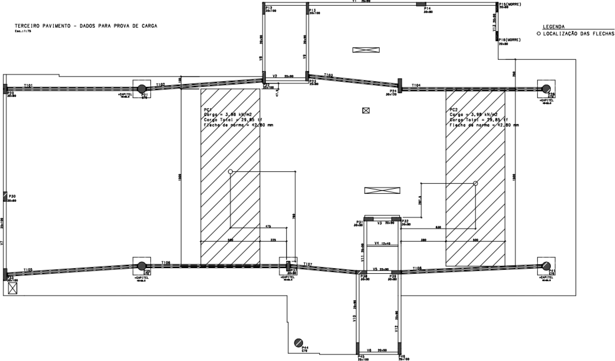
LT1
Slab area
75.00 m²
Total load
29.9 tf
Limit arrow from standard
42.8 mm
Initial arrow (unloaded)
0.0 mm
Time
Date (D/M/Y)
Load
Center deformation (mm)
Edge deformation(mm)
Difference (mm)
Obs.
07:37
03/06/2022
0
0.00
0
0.00
08:16
03/06/2022
25 %
1.88
0.55
1.33
08:30
03/06/2022
25 %
1.97
0.55
1.42
08:42
03/06/2022
25 %
1.99
0.54
1.45
09:25
03/06/2022
50 %
3.76
1.05
2.71
09:40
03/06/2022
50 %
3.79
1.06
2.73
09:49
03/06/2022
50 %
3.77
1.07
2.70
10:20
03/06/2022
75 %
6.49
1.53
4.96
10:34
03/06/2022
75 %
6.46
1.54
4.92
10:48
03/06/2022
75 %
6.45
1.54
4.91
11:12
03/06/2022
100 %
7.34
1.89
5.45
11:28
03/06/2022
100 %
7.37
1.9
5.47
11:45
03/06/2022
100 %
7.37
1.9
5.47
10:37
04/06/2022
100 %
8.20
2.29
5.91
At 24 h
10:14
05/06/2022
100 %
8.24
2.37
5.87
At 48 h
09:28
06/06/2022
100 %
8.25
2.53
5.72
At 60 h
10:49
06/06/2022
50 %
4.54
1.68
2.86
50 % unloaded
13:40
06/06/2022
0
0.78
0.62
0.16
Fully unloaded
18:02
06/06/2022
0
0.67
0.54
0.13
4h after fully unloaded