![]()
| Basic Research | https://doi.org/10.21041/ra.v15i2.738 |
Pathological manifestations in a prestressed concrete flat slab building - a case study: part I - structure analysis
Manifestaciones patológicas en una edificación con losas pretensadas - un estudio de caso: parte I - análisis de la estructura
Manifestações patológicas em uma edificação com lajes protendidas – um estudo de caso: parte I – análise da estrutura
A. B. S. Santos Neto1*, A. Lübeck2, P. J. Sarkis3, J. M. Sarkis3
1 Programa de Pós-Graduação em Arquitetura, Urbanismo e Paisagismo, Universidade Federal de Santa Maria, Brasil.
2 Programa de Pós-Graduação em Engenharia Civil, Universidade Federal de Santa Maria, Brasil.
3 Sarkis Engenharia Estrutural, Santa Maria, Rio Grande do Sul, Brasil.
*Contact author: almir.neto@ufsm.br
Received: 15/05/2024
Revised: 22/03/2025
Accepted: 23/04/2025
Published: 01/05/2025
| Cite as: Santos Neto, A. B. S., Lübeck, A., Sarkis, P. J., Sarkis, J. M. (2025), " Pathological manifestations in a prestressed concrete flat slab building - a case study: part I - structure analysis", Revista ALCONPAT, 15 (2), pp. 123 – 140, DOI: https://doi.org/10.21041/ra.v15i2.738 |
Abstract
Prestressed concrete flat slabs with unbonded tendons are widely used in Brazil due to their advantages. However, the bold achieved with the use of prestressed buildings often results in highly complex projects and non-trivial considerations in the engineer's daily work. This work aims to present a case study of a commercial building constructed in Rio Grande do Sul, consisting of prestressed concrete flat slabs with unbonded tendons, where pathological manifestations occurred even during the construction phase, such as excessive deflections, cracks in the prestressed slabs, and some partial ruptures of structural elements. The work presents the pathological manifestations at the building and the structural analysis, as well as a succinct presentation of the reinforcement techniques used.
Keywords: prestressed concrete flat slab; unbonded tendons; non-adherent post-tensioning; pathological manifestations in concrete structures.
1. INTRODUCTION
Prestressed flat slabs with unbonded tendons have been increasingly used in construction in Brazil. This is a result of the existence of an increasing number of construction companies with the necessary equipment, technical knowledge and the use of specialized software to aid project design. According to Cauduro (2005), the first use of such slab occurred in 1997, making it a little over 25 years of use of this structural system at the time of print. Over these decades, the use of prestressed flat slabs around the world confirmed its practical use and granting of greater architectural freedom. Aalami (2000) noted that the manufacture of high strength steels and development of specific design software made these structures technically and financially accessible, thus allowing their effective application in civil construction.
Prestressing also improves the service limit state (SLS) and structural safety through increased concrete durability: as fissuring decreases or is suppressed, reinforcements are protected from pathological phenomena such as corrosion. However, prestressed structures also allow increased complexity and bolder architectural designs which result in highly complex and non-trivial issues for structural engineers. Furthermore, these issues can also require a high level of technical expertise during execution. Consequently, as the number of construction projects making use of prestressed systems with unbonded tendons increases, there is a trend of increasing pathological phenomena. However, it should be noted that the incidence of these issues are still rare.
In prestressed flat slabs with unbonded tendons, the tendons are usually laid in a parabolic arch which produces eccentricities with respect to the center of the slab. This increases the efficiency of the loads applied by the tendons and increases load bearing balance. The principle behind this concept is to allow prestressed vertical loads to balance some of the permanent applied loads so that, under these conditions, the slab is subjected only to compressive stresses (Silveira, 2002; Aalami, 1990; Aalami and Bommer, 1999).
Thus, it is essential that tendons be laid as distant as possible from the neutral line of the slab but within projected cover limits. Improper vertical placement could allow the occurrence of pathological phenomena, different deflection arrows from projected or even structural collapse (Silva et al., 2018; Aalami and Bommer, 1999; Romanichen and Souza, 2019; Cattelan et al., 2022). Additionally, slender structures do not allow the vertical placement of cables to efficiently balance out structural loads making flat slabs susceptible to pathological phenomena such as excessive deflection arrows and occurrence of fissures.
The purpose of this study was to present a case study of a commercial building constructed with prestressed flat slabs with unbonded tendons and edge beams. During construction, grave pathological manifestations occurred with excessive deflection arrows, fissuring and partial rupturing. This Part I of the study presented descriptions of the pathological manifestations, structural analysis and a brief discussion of proposed reinforcement solutions to the structure.
2. CASE STUDY
2.1 Investigation Methodology
As requested by the owners, a survey and evaluation of the pathological manifestations were conducted in order to determine their causes and possible recovery and reinforcement techniques to be applied. During the survey, all construction work was stopped and the structure partially reinforced with temporary bracings.
In addition to the survey and evaluation of pathological manifestations, structural calculations were performed again taking into consideration materials, design specifications from the original structure and data obtained from the survey. Results from this technical analysis of the structural project confirmed the need of structural reinforcements for the building.
2.2 Case History
The structure of this case study is a commercial building composed of a partially underground level (providing parking spaces, storage, changing rooms, water basin and depository), ground floor (providing public access, reception, auditorium, commercial spaces, restrooms, pantry etc.), 2nd and 3rd floors offices (holding office spaces, meeting rooms, training rooms, coffee break lounge, kitchen, restrooms and an external area split between a green roof area and a restricted access area), top floor with no public access (containing the roof slab and rooftop water reservoir) and an additional waterproof roof slab covering the reservoir.
In total, the structure contained 6 floors with a total constructed area of 5,697.00 m2. Figure 1 presents a side view cross-section containing all floors and Figure 2 presents the superposed floor plans of the 2nd floor (grey) and 3rd floor (orange). A reduction in floor plan occurred from the 3rd floor and higher so that the exposed slabs of the 2nd floor were designated public access terraces. Floor dimensions up to the 2nd floor were 61.15 m by 53.72 m, which decreased to 48.48 m by 29.70 m on the 3rd floor and higher. There were no expansion/isolation joints in the structure.
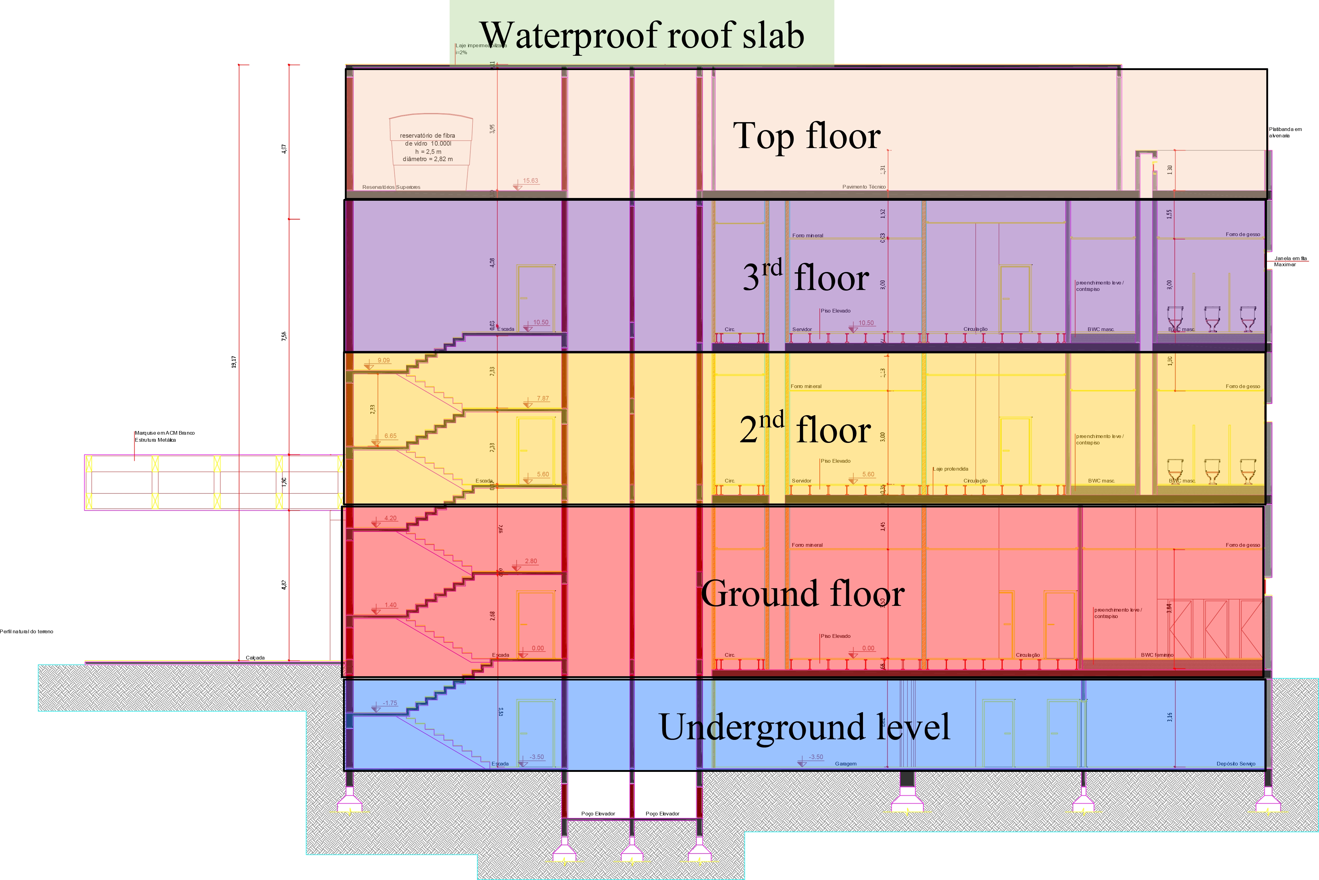
Figure 1. Side cross-view of the structure and floors.
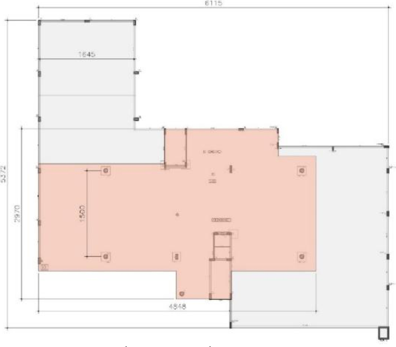
Figure 2. Superposed 2nd (grey) and 3rd (orange) floor plans (units in cm).
The structural project was, in principle, developed in accordance with the applicable version of standard NBR 6118 (ABNT, 2014) at the time. The structural project was categorized as containing prestressed flat slabs with external balancing, few edge beams and capitals in interior columns (characterizing a mushroom slab). Most beams were of reinforced concrete with a single one of prestressed concrete. Slabs were all prestressed concrete except for the reservoir cover which was of reinforced concrete.
Prestressed slabs were 25 cm thick while the reinforced slab over the reservoir was 15 cm thick. Concrete used in the structure was of C35 class (fck = 35 MPa). Unsupported spans in the prestressed slabs were around 15 m with the widest span being 16.45 m over the auditorium (corresponding to the 2nd floor slab).
In accordance with the original structural design, concrete covers were 1.5 cm over passive reinforcement and 3.0 cm over active reinforcement. Unbonded tendons were 12.7 mm in diameter and made from steel CP 190 RB (fptk = 1,900 MPa). Passive reinforcements were made from steel CA-50 (fyk = 500 MPa) and CA-60 (fyk = 600 MPa).
Prestressed cables were more concentrated in one direction and more distributed in the orthogonal direction as shown in Figure 3. Figure 3(a) shows the cable layout for the 2nd floor slab which was similar to the ground floor slab. Figure 3(b) shows the layout for the 3rd floor, which was similar to the rooftop slab.
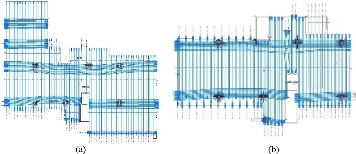
Figure 3. Prestressed cable layout for (a) 2nd floor and (b) 3rd floor slabs.
3. SURVEY OF PATHOLOGICAL MANIFESTATIONS
During construction, pathological manifestations such as excessive deflection arrows, fissures on the slabs, columns and beams and localized ruptures were observed. Figure 4 shows the auditorium cover slab (2nd floor slab) with visible rainwater accumulation. Excessive deformations were noticed on this slab once temporary bracing was removed. The survey determined a deflection arrow of 14 cm at the center of the slab with an unsupported span of 16.45 m. Figure 5 shows the bottom of the slab with temporary bracing restored once the excessive deflections were noted.
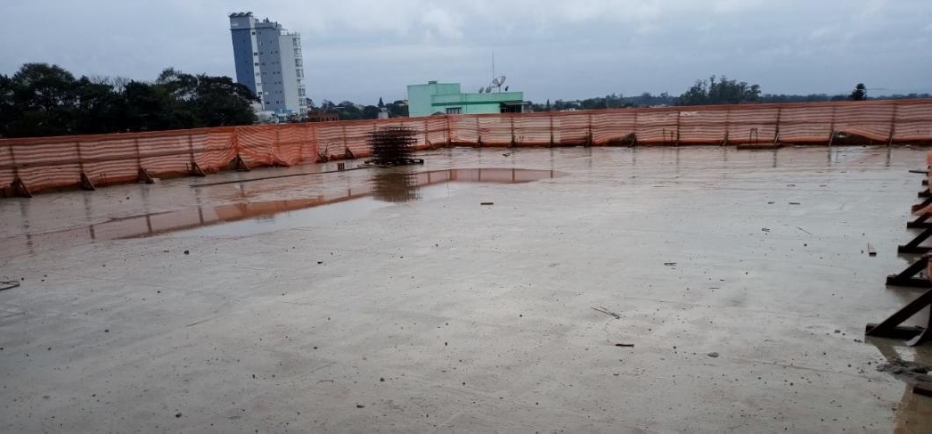
Figure 4. Rainwater accumulation on the cover slab of the auditorium
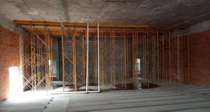
Figure 5. Restored temporary bracing of the cover slab of the auditorium
Figure 6 shows that, at the stage side of the auditorium, shifts of the 2nd floor slab and beams induced a rupture in the beam-column joint. It was likely that the excessive deflection arrow of the auditorium cover slab produced a retraction of the edge beam from the support column. This unpredicted horizontal load then caused the rupture of the beam-column joint.
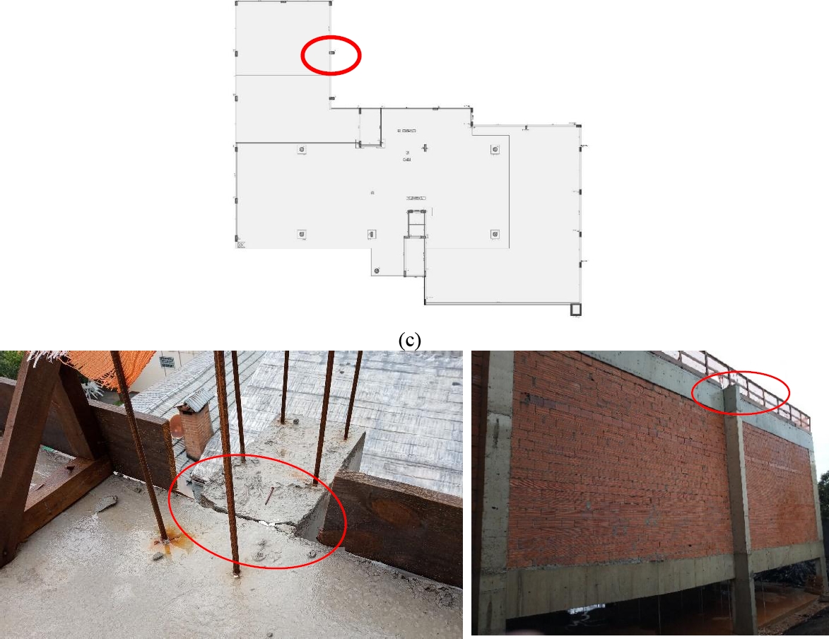
Figure 6. (a) Localized rupture at the beam-column joint; (b) side view of the column with ruptured joint and (c) floor plan location where rupture occurred.
Figure 7 shows that the 2nd floor slab covering the reception area also presented water accumulation and had excessive deflection arrows measured in the order of 10 cm. Intense fissuring was also found on the top and bottom surfaces at the center of the spam and along the edge beams. Curling and fissuring were also observed at the edges of the slab where the tendons were anchored.
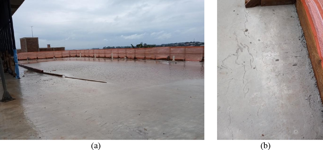
Figure 7. Water accumulation on the cover slab over the reception area; (b) curling and fissuring at the edge of the slab near the columns and anchoring points.
Intense fissuring was also observed on the cover slab over the 3rd floor as shown in Figure 8. These manifestations were noted mostly over the columns.
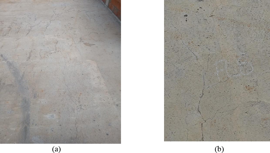
Figure 8. (a) Fissures on the 3rd floor cover slab; (b) surveyed fissure.
The pathological manifestations of Figures 7 and 8 were most likely brought about by the same factors: lack of rigidity in the prestressed slab producing excessive deformation which resulted in twists and plastic behavior at the edges. Along the unsupported span, the excessive deformation produced large fissures surveyed on the top and bottom of the slab. At the edges of the slab, fissures were found to be parallel to the edge beams.
In addition, further fissures were noted on the top of slabs near the columns on the 2nd, 3rd and top cover slabs. Fissuring followed the regular layout of reinforcement and concrete presented deformation and curling. In addition, on the 3rd floor and top cover, further radial fissures were found radiating from the columns. The distribution of fissures and deformations indicated that combined negative moments stressed the top surface of the slab and resulted in punching. It should be noted that the original structural design was later evaluated to contain greatly underestimated negative reinforcements over the columns.
4. TECHNICAL EVALUATION OF THE STRUCTURAL DESIGN
4.1 Initial Evaluation
The first step in the evaluation of the structural design was to compare the thickness (height) of the slab and its type with reference works and standards. The North American ACI 318 standard (ACI, 2019) recommended an unsupported span to height aspect ratio L/h ≤ 42 for floor slabs and L/h ≤ 48 for cover slabs. On the other hand, the PTI Post-Tensioning Institute (PTI, 2023) recommended aspect ratios of 40 ≤ L/h ≤ 45 for floor slabs and 45 ≤ L/h ≤ 48 for cover slabs. Likewise, standard ACI 423 (ACI, 1996) recommended the following aspect ratios for prestressed slabs: 40 ≤ L/h ≤ 45 for floor slabs and 45 ≤ L/h ≤ 48 for cover slabs. Despite recommendations from standards, smaller heights were allowed as long as the slab was checked for deflection arrows and risk of excessive vibrations.
Brazilian standard NBR 6118 (ABNT, 2014) recommended a minimum thickness of 16 cm for flat slabs. While the standard did not directly recommend aspect ratios for prestressed slabs, it did set limits on deflection arrows. In terms of reference studies, Emerick (2005) recommended a minimum thickness of 24 cm for unsupported spans between 10 m and 11 m in prestressed slabs with unbonded tendons. Loureiro (2006) praised flat slabs for their aesthetic, functional and build qualities and recommended their use for unsupported spans up to 8 m. Furthermore, Loureiro (2006) recommended the use of capitals in the case of wider spans of up to 12 m to prevent punching, and prestressed joist slabs with massive column reinforcement for spans wider than 13 m in order to resist negative bending moments and punching effects.
The original structural design established unsupported spans of 16.45 m covering the auditorium and 14.90 m covering the reception. These areas are denoted as “1” and “2” in Figure 9. Throughout all floors, prestressed slabs were uniformly specified to be 25 cm in thickness resulting in aspect ratios (L/h) of up to 65. It should be noted that this slab thickness was below recommended values for the wider unsupported spans of the project. Based on references, the recommended slab thickness should have been around 35 cm (when not using capitals), or the prestressed slab type should have been changed from flat to joist in order to significantly decrease the slab weight. As noted previously, despite recommended standards, thinner slabs could be used if checks on maximum deflection arrows, normal and tangential limit stresses and risk of excessive vibrations were conducted.
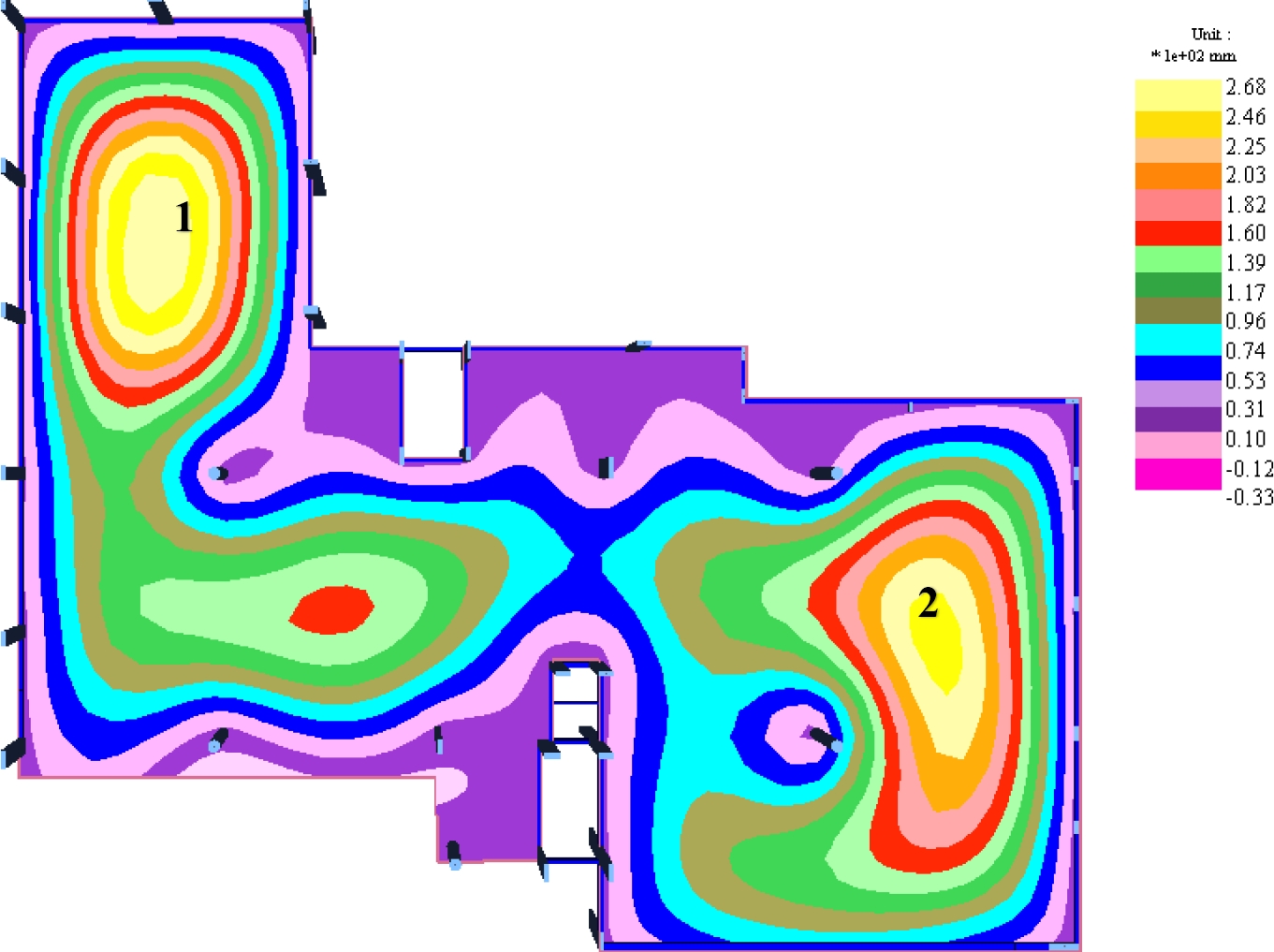
Figure 9. Contours of vertical deflection over time on the 2nd floor slab (values in ×10-2 mm)
4.2 Durability, Concrete Type and Reinforcement Cover
The building was being constructed in an urban area in a city in the countryside of Rio Grande do Sul. According to the version of standard NBR 6118 (ABNT, 2014) applicable at the time, the environmental aggressiveness classification (EAC) of the project was EAC II but the design followed EAC I directives which corresponded to building in a rural zone. This classification allowed thinner cover over reinforcements, higher water/agglomerate ratios and lower compressive strength of concrete.
The compressive strength of concrete (fck) used in the projected structure (slabs, beams and columns) was of 35 MPa which was in accordance with EAC II. However, the protective concrete cover thickness over positive slab reinforcements was 15 mm, lower than the 20 mm required by EAC II. Concrete cover over active reinforcements was 25 mm which was also below requirements from standards. Additionally, the survey and evaluation noted several cables and passive reinforcements with less cover than specified in the original project. This indicated low quality control procedures in execution.
4.3 Loads Considered in the Original Structural Project
Project design started before the current update of standard NBR 6120 (ABNT, 2019) so the previous version of standard NBR 6120 (ABNT, 1980) was used to calculate the loads. The main observations noted in the evaluation of the original design project were:
a) Permanent loads did not account for the weight of leveling compound for the restrooms, terraces and green roof area. The use of a leveling compound was cited in the architectural project but was absent from the structural project. Estimates on the weight of the compound resulted on a load higher than 4.0 kN/m² in some areas such as the audience in the auditorium;
b) The composition and weight of the stage of the auditorium was not mentioned in the structural project and apparently not included in the structural project. The stage was constructed from masonry blocks, a pre-fabricated slab from EPS blocks and concrete joists and a mortar smoothing layer;
c) The structural project did not evaluate stresses induced by concrete shrinkage nor detailed building procedures to minimize this effect. Also, no information was found on the effect of loads caused by thermal variations;
d) There were no mentions of overloads in each area. Since the project included public assembly areas such as the auditorium and terraces, these loads would be considerable.
4.4 Structural Analysis of the Building
The structural analysis involved different methodologies and software. Prestressed slabs were analyzed separately using Adapt Floor Pro 2018 software and automatic mesh generation. A finite element method (FEM) was used with thin-plate elements limited in maximum size to 30 cm. Beams, columns and global behavior were evaluated with FEM 1-D elements on AltoQi Eberick V21 software. Finally, stresses from thermal variations and shrinkage were analyzed on SAP 2000 V18 software with a FEM spatial frame.
The computational model included all information contained in the original structural project: element sizes, active reinforcements and cable layout and reinforcement cover. Strength and modulus of elasticity of concrete were determined from destructive and non-destructive tests on extracted samples and application of a Schmidt rebound hammer. However, the original projected loads were not used since they did not account completely to the architectural project and what was surveyed in loco. The loads used in the model were corrected with the observations presented in Sec. 4.3.
The modeled slab was assumed to be prestressed limited in order to conform with the serviceability limit state of fissuring (SLS-F) for prestressed flat and mushroom slabs as noted in Sec. 13.4.2 of standard NBR 6118 (ABNT, 2014). The SLS-F was defined as the state at which fissures appear in the concrete and it was agreed on that this state occurred when the maximum tensile stress in the cross section was equal to the flexural bending strength of concrete (fct,f).
The model assumed the same cement CPV-ARI used in the building, prestress applied at 10 days of age and projected concrete strength fck = 35 MPa. Thus, the maximum tensile stress of the concrete (SLS-F at t∞) was calculated as:
The serviceability limit state of excessive compression (SLS-EC) is defined as the state at which compressive stresses reach limits set by standards. Usually, this state is reached only when prestresses are applied on the slab and standard NBR 6118 (ABNT, 2014) does not set a limit for maximum compressive stress on concrete under service loads.
The ultimate limit state (ULS) was also checked with respect to the conditions set by Sec. 17.2.3 of NBR 6118 (ABNT, 2014). In this case, the ultimate limit state at presstressing (initial stress) was taken from Sec. 17.2.4.3.2 of NBR 6118 (ABNT, 2014) under the following conditions:
a) maximum compressive stress in the concrete section taken with weight factors of γp = 1.1 and γf = 1.0 could not exceed 70 % of the characteristic strength fckj predicted at the age when prestress was applied;
b) maximum tensile stress on concrete could not exceed 1.2x the tensile strength fctm for the corresponding fckj.
Thus, the maximum compressive and tensile stresses of the concrete at ULS-AP (to), calculated in accordance with Sec. 12.3.3 of NBR 6118 (ABNT, 2014), were:
- maximum compressive stress of concrete:
- maximum tensile stress of concrete:
Limits for vertical deflections (arrows) were set by standard NBR 6118 (ABNT, 2014). Since there was an increasing trend of deformations over time, these values were determined with a multiplication factor (ϕ = 2.0) recommended by standard ACI 318 (ACI, 2019). This allowed shrinkage and slow concrete deformation to be accounted for in deflection arrow calculations over time in a quasi steady-state (QSS) condition.
It should be noted that this condition could underestimate deflection arrows on a prestressed structure due to the limited prestressing applied under SLS-F – meaning no fissure formation on the element. However, the analysis indicated that the structure would present fissures, which were confirmed in loco. Thus, the deformations measured in loco tended to be higher than the ones calculated in the analysis for the model conditions since fissuring decreased rigidity of the elements.
Due to the size of the building, this study presented only the analysis of the 2nd floor slab. This slab was chosen since it corresponded to the roof of the auditorium and contained the widest unsupported spam of the structure. The selected results were deflection arrows and normal stresses on the 2nd floor slab. It should be noted that similar results were found on the slabs of the other floors.
The deflection arrows calculated from the model were compared to the limits set by standard NBR 6118 (ABNT, 2014). The analysis was conducted in critical regions with higher deflections and wider unsupported spans. The same procedure was applied to maximum and minimum normal stresses.
4.4.1 Results for the 2ndFloor Slab
a) Vertical Deflection (Arrows)
Figure 9 presents a top view of the 2nd floor slab with isocontours of vertical deflection over time.
Figure 9 shows that region 1, which corresponded to the cover over the auditorium and had an unsupported spam of 16.45 m, had a maximum deflection arrow over time of 26.8 cm. Standard NBR 6118 (ABNT, 2014) set the acceptable limit for visible deflections as a ratio equal to spam/250, which in this case would result in a deflection of 6.58 cm. Thus, the analysis denoted a much higher deflection than allowed in the standard and, while the survey measured a deflection of 14 cm at the construction site, this was a result of only the slab’s own weight and did not include all additional structural and architectural elements.
Similarly, Figure 9 shows that region 2, which corresponded to the cover over the reception area and had an unsupported span of 14.90 m, had a maximum deflection arrow over time of 26.8 cm. Following the same criteria from standard NBR 6118 (ABNT, 2014), the maximum acceptable visual deflection should have been 5.96 cm. Thus, region 2 presented the same above allowed deflection arrow issues as region 1.
b) Normal Stress Limits
Figure 10(a) shows normal stresses on the top surface of the 2nd floor slab for loads applied along the x-direction of the figure while Figure 10(b) shows the corresponding normal stresses from loads applied in the y-direction. The corresponding normal stresses on the bottom surface of the slab are shown in Figure 11(a) and 11(b), respectively.
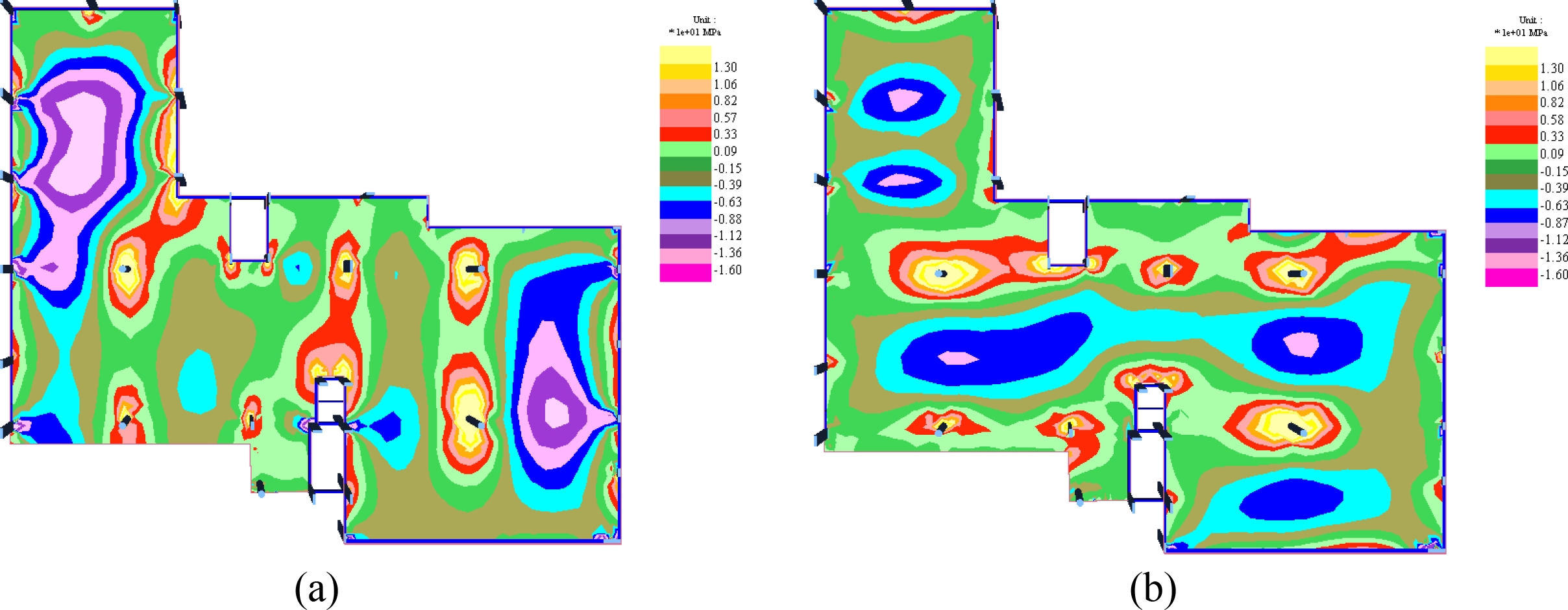
Figure 10. Normal stresses (×10 MPa) on the top surface of the 2nd floor slab (a) from loads in the x-direction and (b) loads in the y-direction.

Figure 11. Normal stresses (×10 MPa) on the bottom surface of the 2nd floor slab (a) from loads in the x-direction and (b) loads in the y-direction.
Results of Figure 10 show that the maximum tensile stresses on the top surface of the slab were between 9.0 MPa and 12 MPa around the columns in the right side of area 1 (over the auditorium) and between 8 MPa and 12 MPa in area 2 (over the reception). The location of these high stress values also corresponded to where fissures were found in the survey. Results of Figure 11 show that tensile stresses on the bottom surface of the slab were in the order of 10.0 MPa in area 1 and 8 MPa in area 2. Tensile stresses on the face of edge beams were also found to be in the order of 10 MPa.
Figures 10 and 11 demonstrated that normal stresses in some areas of both top and bottom surface of the slab exceeded the recommended tensile limit of 3.37 MPa and the tensile strength of the concrete. This condition is further confirmed by the fissures observed on both top and bottom surfaces of the slab during the survey. However, with respect to ULS-AP, the maximum tensile and compressive stresses in the analysis were within limits set by standard NBR 6118 (ABNT, 2014).
c) Positive Passive Reinforcement
The structural project proposed a Q196 welded steel reinforcement mesh with a surface area of 1.96 cm²/m in either direction as positive passive reinforcement for the 2nd slab. The numerical analysis indicated that such reinforcement would be insufficient for all areas of the 2nd floor slab, which in some areas reached a maximum requirement of 12.5 cm²/m.
d) Negative Passive Reinforcement
The structural project proposed a mesh with bars f 12.5 mm spaced 15 cm apart for a surface area of 8.3 cm²/m as negative passive reinforcement over internal columns not connected by beams. The structural analysis was not able to calculate a feasible negative passive reinforcement with commercially available diameters and spacing that would be able to sustain the 25 cm thick slab and loads predicted in the architectural project over some columns. Thus, no negative passive reinforcement suggestion was proposed for the existing structural elements.
4.4.2 General Observations on Floor Slabs
a) Analysis of Slab Punching and Progressive Collapse Reinforcement
Reinforcements against punching and progressive collapse were present in the original structural project and were also subjected to analysis. The analysis followed the recommendations of standard NBR 6118 (ABNT, 2014) with loads obtained from ADAPT Floor Pro 2018 software and checked with TQS – LPUNC application.
The original structural project adopted simple vertical stirrup reinforcements to prevent punching. These reinforcements were proposed to have diameters of 8.0 mm, 10.0 mm and 12.5 mm. The type of reinforcement and proposed diameters were in accordance with Sec. 20.4 of NBR 6118 (ABNT, 2014) which recommended that reinforcement diameter not exceed 1/20 of the slab thickness.
The original structural project presented ground floor reinforcement against punching and progressive collapse in accordance with NBR 6118 (ABNT, 2014). However, 2nd floor analysis indicated that two columns required an increase of around 12 % in reinforcement against progressive collapse as the original values were adequate only against punching. For the 3rd floor, the analysis identified the need of a 25 % increase in reinforcement in a single column to protect against progressive collapse while the original design was adequate against punching. The top cover floor had the most discrepancies in the original structural design. The analysis indicated that about half of the slab/column interfaces required around 11 % increased reinforcement to protect against punching. Progressive collapse protection as recommended by Brazilian standards was adequate in only one slab/column interface and all other interfaces required increased reinforcements of as much as 45 %.
b) Shear Reinforcement and Reinforcement at Holes and Openings.
Section 19.3.3.2 of standard NBR 6118 (ABNT, 2014) recommended adding negative reinforcement at the connection between the edge of the slab and support beams in order to decrease the possibility of fissuring from the partially rigid connection between the slab and beams. This reinforcement was not found in the documents that comprised the original structural project. Since the slabs underwent considerable deflection, the twist induced along the connection produced large negative moments which, in the absence of shear reinforcement, produced fissures around the perimeter of the elements.
Section 20.2 of standard NBR 6118 (ABNT, 2014) established that free edges and solid slab faces near openings must be adequately supported with longitudinal and cross reinforcements. Such reinforcements were also not mentioned in the original structural project and the survey found fissures on the slab starting from the corner of openings.
4.4.3 Shrinkage and Thermal Effects on the Structure
Shrinkage and thermal effects were analyzed with SAP 2000 V18 software. Thermal effects were applied as uniform variations in temperature in increments of ±15 °C. Shrinkage was simulated as the slab being subjected to an ambient temperature of -30 °C with a relative humidity of 75% and time t0 of 60 days as specified in Table 8.2 of standard NBR 6118 (ABNT, 2014). Results determined that on the ground and 2nd floor, where the entire length of the structure exceeded 60 m, shrinkage and thermal effects were significant. Figure 12 presents the displacements in the (horizontal) x-direction of the ground floor slab considering the permanent load, prestress and shrinkage in a 1:1:1 additive combination. Under these conditions, the maximum shrinkage calculated in the analysis was 1.4 cm.
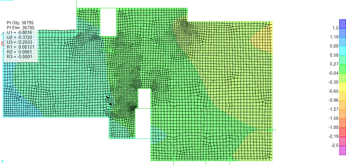
Figure 12. Ground floor slab displacements in the (horizontal) x-direction for a combination of loads and shrinkage (units in cm).
Figure 13 shows the result of the same load combination on the displacement in the (horizontal) x-direction for the 2nd floor slab. In this case, the maximum shrinkage was calculated to be up to 1.3 cm.
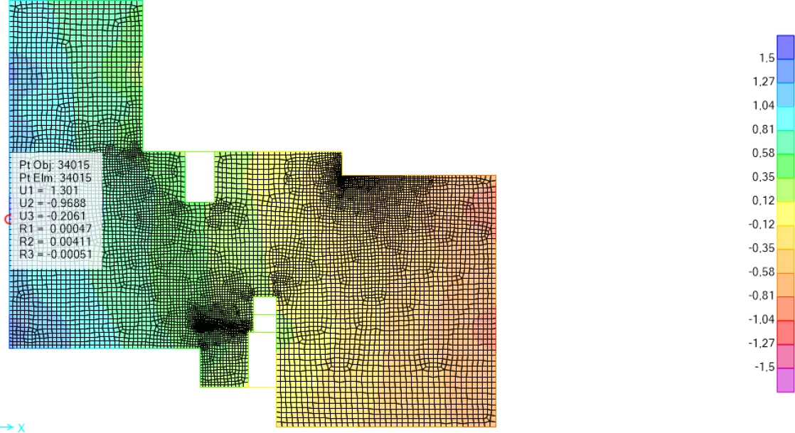
Figure 13. 2nd floor slab displacements in the (horizontal) x-direction for a combination of loads and shrinkage (units in cm).
Shrinkage tended to produce horizontal loads in the connections between the slab and columns. An analysis of the columns in the underground garage and ground floor determined high transversal loads which, for some columns, were 25 % above the load bearing capacity of the element. Since the survey identified fissures at the top of some of the garage columns, this was likely caused by shrinkage. These columns were repaired and reinforced as shown in Part II of this study.
5. REPAIR AND REINFORCEMENT OF THE STRUCTURE
After the survey of pathological manifestations, a repair and reinforcement project was elaborated and presented in Part II of this study. Different strategies were employed such as applying (cut in) carbon fiber overlays and tapes, metallic beams and columns, prestressed metallic trusses and external prestressed tendons with deviators. Once the reinforcements were installed, new load tests were performed on the structure to confirm the effectiveness of the work.
In general, the reinforcement strategy relied on mounting steel reinforced concrete trusses under the slabs at the same locations as prestressed cables. This increased the rigidity of the slab at these points. Similarly, external prestressed tendons with deviators were mounted under the slabs to apply upward loads. The combination of trusses and external prestressed tendons returned the slabs to the original projections and decreased deflection arrows to levels in line with standard NBR 6118 (ABNT, 2014).
While trusses and external prestressed tendons repaired deformation and rigidity issues, acting loads were countered with appropriately sized carbon fiber reinforcements. Carbon fiber overlays were bonded to the bottom surface of the slabs to replace the missing passive reinforcement while cut in carbon fiber tape was inserted to the top surface of the slabs to replace the missing negative reinforcements.
Columns in need of reinforcement were dealt with in accordance with geometry. Round columns were reinforced with T-shaped metallic profiles inserted lengthwise along the surface and held in place with carbon fiber belts. Rectangular columns were reinforced with L-shaped metallic profiles bonded lengthwise at the corners and also held in place with carbon fiber belts.
6. FINAL CONSIDERATIONS
The technical analysis of the original structural project indicated that the proposed slab thickness was lower than recommended in references and standards and resulted in slabs more flexible than ideal. The prestressed mushroom slab adopted could also have been improved if a joist system had been adopted, which would have significantly decreased the weight while also allowing a thicker slab to be used without an increase in permanent loads. It should be noted that thinner slabs could be used in contradiction to references if maximum deflection arrows, normal stress limits and risk of excessive vibrations were kept under check. A thicker slab would have produced lower deflection arrows and decreased normal tensile stresses to levels within standards. A thicker slab would also allow higher eccentricity of the prestresses cables which would improve load balancing and the effect of prestressing.
Part I of this study focused on the 2nd floor slab. However, the pathological manifestations surveyed were also present on the other floors of the structure. At regions of the slab, fissuring normal stresses (SLS-F) exceeded the standard tensile limit of 3.37 MPa by a wide margin. This produced fissures on both top and bottom surfaces of the slab as noted in the survey. However, the analysis also indicated that the maximum ULS-AP values for both tension and compression remained below limits set by standards.
Regarding passive reinforcement, the analysis concluded that positive reinforcements were insufficient over all slabs. Additionally, no negative reinforcement was able to be proposed due to the thinness of the slab in the original structural project.
Structural analysis regarding protection against punching and progressive collapse indicated that the original structural project agreed with standards for most beam/column connections. However, two columns on the 2nd floor were found require around 12 % further reinforcement against progressive collapse.
After the structural analysis of the original structural project, a reinforcement project was elaborated. The reinforcement project made use of several strategies such as the addition of carbon fiber overlays bonded to the slabs, cut in carbon fiber tape inserts, external prestressed tendons with deviators and trusses with metallic reinforcement. The external presstessed reinforcements and trusses were also used to decrease the surveyed deflections in the slabs.
After execution, the reinforced structure was tested under loads to evaluate its performance. Part II of this study presented the techniques used in the reinforcement and the structural re-evaluation.
7. REFERENCES
Aalami, B. O. (1990), Load Balancing: A Comprehensive Solution to Post - Tensioning. ACI Structural Journal: 662-670.
Aalami, B. O. (2000), Structural Modeling of Post-Tensioned Members. Journal of Structural Engineering, vol. 126 nº 2, pp. 157-162.
Aalami, B. O., Bommer, A. (1999), “Design Fundamntals of Post-Tensioned Concrete Floors”. Post-Tensioning Institute (PTI), Farmington Hills, USA.
American Concrete Institute (2019). ACI 318 - Building Code Requirements for Structural Concrete. Farmington Hills, MI.
American Concrete Institute (1996). ACI 423 – Recommendations for Concrete Members Prestressed with Unbounded Tendons. Commitee 423. Detroid.
Associação Brasileira de Normas Técnicas. (2019). NBR 6120: Ações para o cálculo de estruturas de edificações. Rio de Janeiro.
Associação Brasileira de Normas Técnica. (1980). NBR 6120: Cargas para o cálculo de estruturas de edificações. Rio de Janeiro.
Associação Brasileira de Normas Técnicas. (2014). NBR 6118: Projeto de Estruturas de Concreto – Procedimento. Rio de Janeiro.
Associação Brasileira de Normas Técnicas. (2023). NBR 6118: Projeto de Estruturas de Concreto. Rio de Janeiro.
Cauduro, E. L. (2005), “Manual para a Boa Execução de Estruturas Protendidas Usando Cordoalhas de Aço Engraxadas e Plastificadas”. 2ª Edição. p109.
Cattelan, R. A., Cielo, L., Lübeck, A., Santos Neto, A. B. (2022). “Analise da influência da variação de excêntricidade de cordoalhas engraxadas no comportamiento estrutural de lajes lisas protendidas”. Revista ALCONPAT. 11 (2), pp. 210 – 226. https://doi.org/10.21041/ra.v12i2.570.
Emerick, A. A. (2005), “Projeto e Execução de Lajes Protendidas”. Ed. Interciência. Rio de Janeiro, Brasil, p. 191.
Loureiro, G. J. (2006). “Projeto de lajes protendidas com cordoalhas engraxadas”. In: VI Simpósio EPUSP sobre Estruturas de Concreto. p. 1734-1755. Universidade de São Paulo – Escola Politécnica da Universidade de São Paulo. São Paulo.
Romanichen, R. M., Souza, R. A. (2019), Reinforced concrete corbels strengthened with external prestressing. Revista Ibracon de Estruturas e Materiais. V. 12. N. 4, p. 812 – 831. https://doi.org/10.1590/S1983-41952019000400006.
Silva, G., Prata, B., Albuquerque, A. (2018), Análise da eficiência dos sistemas estruturais para edifícios em concreto. Ambiente Construído. Vol. 18, n. 1, p. 313-325. https://doi.org/10.1590/s1678-86212018000100223.
Silveira, M. C. A. (2002). “Práticas de Projeto e Execução de Edificações Protendidas com Cordoalhas Engraxadas e Plastificadas”. Revista Ibracon de Estruturas e Materiais. 44º Congresso Brasileiro do Concr. Belo Horizonte.