| Casos de Estudio | https://doi.org/10.21041/ra.v12i2.571 |
Concrete degradation by the formation of biogenic sulfuric acid in a Sewage Pumping Station
Degradación del hormigón mediante la formación de ácido sulfúrico biogénico en una Estación de Bombeo de Aguas Residuales Degradação do concreto através da formação de ácido sulfúrico biogênico em uma Estação Elevatória de Esgoto
Gabriella
de Andrade Coni1
*
![]() ,
Amanda
Tafuri Costa2
,
Amanda
Tafuri Costa2
![]() ,
Adriana
Gonçalves Costa1
,
Adriana
Gonçalves Costa1
![]() ,
Guilherme
Sakuma1
,
Guilherme
Sakuma1
![]()
1 Companhia de Saneamento Básico do Estado de São Paulo S.A (Sabesp), São Paulo, State of São Paulo, Brasil.
2 Escola Politécnica da Universidade de São Paulo, São Paulo, Brasil.
*Contact author: conigabriella@gmail.com
Reception:
December
06,
2021.
Acceptance:
March
04,
2022.
Publication: May 01, 2022.
| Cite as: Coni, G., Tafuri, A., Costa, A., Sakuma, G. (2022), "Concrete degradation by the formation of biogenic sulfuric acid in a Sewage Pumping Station", Revista ALCONPAT, 12 (2022), pp. 279 – 295, DOI: https://doi.org/10.21041/ra.v12i2.571 |
Abstract
This work presents the study carried out in a Sewage Pumping Station after severe degradation was observed. The attack by biogenic sulfuric acid in sanitary sewage systems is widely studied in the literature, however, data on real work situations are still quite limited. Analyzes of the concentration of H ퟐ 퐒 in the air, carbonation depth, compressive strength, petrography, SEM/EDS, XRD and chemical determinations were carried out in concrete cores extracted above the effluent level. The products identified on the surface were Gypsum, Jarosite, Ferrous Hydroxide, Ferrous Chloride and possibly Hisingerite. The results demonstrate the presence of products on the surface, from the dissolution of cement paste as well as from the 16 mm steel bars located in the attacked region.
Keywords:
biogenic sulfuric acid attack,
degradation,
reinforced concrete
1. Introduction
The sanitary sewer environment favors the formation of biogenic sulfuric acid (H 2 SO 4 ) due to the presence of sulfur-oxidizing and sulfate-reducing bacteria (Estokova et.al., 2012). This acid produced by oxidizing bacteria is extremely aggressive to concrete as it attacks the cement paste, decalcifying the cement hydration products and leading to a progressive disintegration of the material (Wu et.al., 2018).
Another critical point is the reduction of the pH of the concrete to an extremely low value, reaching values around pH 1-2. Consequently, the depassivation of the reinforcement occurs and the oxidation process begins (Estokova et.al., 2012). So, the acid attacks the concrete as well as the steel bars in a short period, being able to reach deterioration rates of 12 mm/year in many sanitary sewage systems (Wu et.al., 2018). In a study conducted by Fernandes et.al., (2012), a 300 km-long sewage system showed superficial deterioration of concrete just 2 years after its construction. Strategies are currently being studied to mitigate the degradation of sewage infrastructure, for example, the use of bio-concretes that reduce the number of sulfur-oxidizing bacteria (Song et.al., 2021).
The degradation process of concrete by biogenic sulfuric acid, despite being widely discussed in the literature, data from research carried out in real situations are still quite limited (O'Connell et.al., 2010; Wu et.al., 2020). According to Wu et.al., (2020), the corrosion rates obtained in the site and laboratory tests generally show great variation and it is still difficult to establish a quantitative relationship between them based on existing knowledge. This paper presents a case of study in a Sewage Pumping Station from the Basic Sanitation Company of São Paulo State - SABESP severely deteriorated within only 20 years of construction and operation. It is expected that the results from this study will provide parameters able to validate experiments carried out on laboratory scale and further enable the development of strategies to increase the service life of sanitary infrastructures.
2. Fundamentals of sewer corrosion
The attack of biogenic sulfuric acid begins with the formation of aqueous hydrogen sulfide (H2S) by the activity of anaerobic sulfate-reducing bacteria, e.g. Desulfovibrio desulfuricans, present on the slime layer - below the waterline (Wu et. al., 2018). These bacteria, under anaerobic conditions and with a dissolved oxygen concentration (DO) lower than 0.1mg/L, convert the sulfur compounds present in the waste stream to aqueous hydrogen sulfide (H2S)(aq) (House and Weiss, 2014; Wu et.al., 2018).
Part of the H2S (aq) is released from sewage into the gas phase H 2 S (g) above the waterline. The passage of H2S (aq) to the gas phase is strongly influenced by the pH of the wastewater, as well as the equilibrium conditions between the gas and liquid phase, temperature, and turbulence of the flow (Wells et.al., 2009; Wu et.al., 2020). The released hydrogen sulfide condensate on the concrete surface where it is subjected to multiple stages of oxidation by sulfur-oxidizing microorganisms, such as species of the aerobic bacteria Thiobacillus, which act in different pH ranges, converting it to sulfuric acid (House e Weiss, 2014; Monteny et.al., 2000; Wu et.al., 2018).
The colonization of microorganisms in concrete depends on the availability of nutrients (organic matter), moisture, and the reduction of pH. The reduction of the pH of the concrete occurs by the carbonation and by the acidification of the surface caused by the H 2 S (g) (Jiang et.al., 2014). When the surface pH is lowered to ~ 9, the environment already presents sufficient conditions to initiate the colonization of Thiobacillus thioparus (Wu et.al., 2018).
Hereafter, bacterial activity is responsible for governing the gradual pH decrease of the concrete surface simultaneously altering the microbial communities. Thiobacillus novellus, Thiobacillus intermedius and Thiobacillus neapolitanus bacteria start to proliferate until reaching pH ≈ 3.0, then there is a decline in the bacteria previously colonized, resulting in rapidly increasing proliferation of Thiobacillus thiooxidans bacteria, whose presence is associated with severe corrosion (Scrivener and Belie, 2013).
Portlandite Ca(OH)2 , which is mainly responsible for the alkalinity (pH ≈ 13.0) of the cement matrix, is the first compound to react with sulfuric acid, forming gypsum CaSO4. 2H2O. Subsequently, gypsum can react with aluminate-containing phases to form ettringite CaO3. Al2 O3.(CaSO4)3. 32H2O)(House and Weiss, 2014; Wells et.al., 2009). The formation of ettringite results in expansive pressure that can lead to internal cracking of the concrete, allowing the penetration of more acid and the degradation of the structure (Wu et.al., 2018). Furthermore, if pH falls below 10.6, ettringite turns out unstable and starts to dissolve (Duchesne and Bertron, 2013). For that reason, ettringite is an intermediate product, and gypsum is the final product of the sufuric acid attack (Davis et.al., 1998). As the reserve of calcium ions provided a priori by Portlandite is consumed, the following reactions focus on the decalcification of hydrated calcium silicate (C-S-H), the major product of Portland Cement responsible for the concrete mechanical strength. The product of this reaction is silica gel, a material with no bearing capacity (Monteny et.al., 2000). In summary, the degradation of the concrete occurs above the waterline, starting from the surface and gradually advancing inside the structure.
3. Methodology
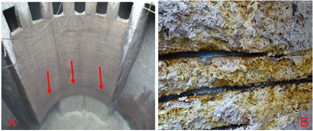
This paper presents a case study on a strongly deteriorated wet-well of a Sewage Pumping Station from the Basic Sanitation Company of São Paulo State (SABESP) put into operation in December of 1999. Internal inspections of the structure were carried out to obtain photographic records and extract concrete core from wet-well’s wall for analysis.
 |
||||
| Figure 1. (a) wet-well (b) Degradation of concrete and steel bars observed by site inspection | ||||
The structure has two concentric circular wells, dry and wet, with a diameter of 25.60 m and 13.70 m, respectively. The first was built in reinforced concrete, with a metallic cover, and the second one in prestressed concrete. The dry well is where six sets of pumps are located and the wet well, the object of this study, with 18.70 m in height, is the part of the structure that receives and sends the sewage to the treatment plant.
The inspection of the structure was carried out in the wet well (Figure 1a) and restricted to the gas area (above the waterline). In this region, the concrete surface presented an atypical condition with layers up to 15 cm thick with no cohesive properties, very easy to remove with a spatula (Figure 2a). The wall’s thickness specified in the project is 35 cm. The passive reinforcement with 16 mm diameter was oxidized (Figure 2b), with loss of section and sectioned and/or completely dissolved parts.
 |
||||
| Figure 2. (a) removal of the degraded concrete layer using a spatula and (b) parts of completely reinforcement dissolution | ||||
The following tests were performed in the present study:
3.1 Gas concentration
Daily measurements of hydrogen sulfide (H2S) concentrations were carried out in the headspace of the pumping station, during the period 02/07/2020 to 11/30/2020, by using myDataSens H2S from Microtronics, with a measurement capability ranging from 0-1000 ppm. The equipment automatically collects and stores data every 5 minutes.
3.2 Carbonation front
The qualitative test to determine the carbonation front of the concrete was carried out using a solution composed of phenolphthalein, which is a colorless acid/base indicator that changes its color to purple at pH above 9 (alkaline), indicating the presence of Ca(OH)2.
3.3 Compressive strength
Four (04) cylindrical concrete cores were extracted for a compressive strength test, according to ABNT NBR 7680-1/15, from the wall with a nominal diameter of 75 mm. The compression test of cylindrical specimens was performed in accordance with ABNT NBR 5739/18.
3.4 Petrographic analysis
The petrographic analysis was based on ASTM C 856/2017 - “Standard Practice for Petrographic Examination of Hardened Concrete”. Two of the extracted concrete cores were used to make thin sheets with dimensions of 2.5 cm x 4.0 cm to characterize the interface between the sound and attacked concrete. A microscope model DM4500 P coupled to a digital camera DFC7000 T, both from Leica, and a stereoscopic binocular magnifier model M-8, from Wild, were used. Image editing was performed using the LAS X software. The photographic technique through photomicrography was used in the test to obtain enlarged images of the material's microstructure.
3.5 Scanning electron microscopy, X-ray diffraction and chemical determinations
In the same core, analyzes were carried out in three different layers: an outer layer, obtained by scraping the concrete with no cohesive properties; an intermediate layer; and an inner layer, apparently not attacked. For scanning electron microscopy, the scraped sample was dried in a sealed desiccator at room temperature for 4 days. The dry fragments were carefully mounted in the aluminum sample holder, with the aid of carbon tape and aluminum tape. The intermediate and innermost samples were broken with the aid of a hammer, at each end of the concrete core. The fragments were collected, carefully selected, and promptly mounted in an aluminum sample holder, with the aid of carbon tape and aluminum tape and covered with a thin layer of gold-palladium.
For the X-ray diffraction analysis, an aliquot of the scraped sample was dried at (45±5) ºC for 7 days, while the fragments of the intermediate and innermost samples were crushed in a mortar to obtain the mortar, then they were grounded in a porcelain mortar until completely passed through an ABNT No 200 sieve (75 μm). The EMPYREAN model Panalytical X-ray diffraction equipment was used, operating in copper Kα radiation at 45 kV - 40 mA and scanning at 2° 2θ/min. The identification of compounds was performed using Panalytical's X-pert HighScore Plus software (version 4.9) and diffraction patterns provided by the ICDD (International Center for Diffraction Data) with update until 2017.
Chemical determinations were performed only on the scraped material, as follows:
Determination of water-insoluble residue in acid, based on the general guidelines of ASTM C114-18 "Standard Test Methods for Chemical Analysis of Hydraulic Cement" and ABNT NBR 13810:1997 "Water - Determination of metals - Atomic absorption spectrometry method by flame". Determination of sodium (Na), potassium (K), iron (Fe), magnesium (Mg) and calcium (Ca), soluble in water and acid, based on general guidelines from ASTM C114-18 "Standard Test Methods for Chemical Analysis of Hydraulic Cement" and ABNT NBR 13810:1997 "Water - Determination of metals - Flame atomic absorption spectrometry method". Determination of soluble chloride ions and sulfate ions, according to the general guidelines of NBR 9917:2009 "Aggregates for concrete - Determination of soluble salts, chlorides and sulfates".
4. Results and discussion
4.1 Gas concentration
Hydrogen sulfide concentration in the air tends to increase with the temperature, as observed in figure 3. The increase in temperature reduces the solubility of H 2 S (aq) in wastewater and encourages the release in the gaseous form H 2 S (g) (Wu et.al., 2018). However, the temperature is not the only influencing factor, since the concentration of H 2 S(g) inside the Sewage Pumping Station is also influenced by turbulence, which is directly related to the number of pumps in operation at the time of measurement.
 |
||||
| Figure 3. H2S concentration and temperature over the months | ||||
4.2 Carbonation front
After removing the layer with no cohesive properties of approximately 8 cm from the wet-well’s wall, it was observed that the concrete was carbonated as it did not change color with the phenolphthalein’s solution application. Then, a 5 cm hole was made, observing that the innermost region of the concrete was still alkaline, as illustrated in Figure 4.
 |
||||
| Figure 4:. wet-well’s wall - alkaline concrete | ||||
4.3 Compressive strength of concrete
In the compressive strength tests results, illustrated in Table 1, it was observed that all the extracted cores presented higher strengths than those specified in the project (20 MPa). Despite the atypical condition observed on the surface of the concrete, this result was already expected, since the part used in the test was the inner part of the sample, which did not appear to have been contaminated by biogenic sulfuric acid yet.
| Table 1. Direct compressive strength results | |||||||||||||||||||
| ID | Wide (cm) | Timber cant (cm) | Length (cm) | Damages | |||||||||||||||
|---|---|---|---|---|---|---|---|---|---|---|---|---|---|---|---|---|---|---|---|
| VA-1 | 15 | 19.5 | 312 | Splintered by UND at 70 cm from head A. | |||||||||||||||
| VA-2 | 16 | 20 | 320 | Discontinuous longitudinal cracks in the middle of the depth of the LAS, from head B to a length of 250 cm. | |||||||||||||||
| VA-3 | 18 | 20 | 309 | Longitudinal discontinuous cracks in the middle of the depth. | |||||||||||||||
| VA-4 | 17.5 | 20 | 295 | Shredded in TOE throughout the length of the beam. | |||||||||||||||
| VA-5 | 17.5 | 20 | 310 | Discontinuous longitudinal cracks and fissures by LAS, in the middle of the depth. Shredded by TOS from head B to a length of 70 cm. | |||||||||||||||
| VA-6 | 14 | 20 | 304 | Crack in the LAS, from head B to a length of 20 cm in the middle of the superelevation. | |||||||||||||||
| VA-7 | 12.5 | 20 | 304 | Longitudinal crack in the middle of the depth of both lateral faces, from head A to a length of 90 cm. | |||||||||||||||
| VA-8 | 12.5 | 20 | 310 | Longitudinal cracks from head B to a length of 60 cm in the upper half of the LAS. LAS rot from head A, up to a length of 70 cm. | |||||||||||||||
| VA-9 | 14.5 | 20 | 309 | No damages were observed. | |||||||||||||||
| VA-10 | 15.5 | 20 | 310 | Longitudinal fissure in the upper half of the LAS, along the entire length. Superficial shredding by LAS, 90 cm from head B. | |||||||||||||||
| VA-11 | 17.5 | 21 | 310 | No damages were observed. | |||||||||||||||
| VA-12 | 17 | 20 | 310 | ||||||||||||||||
| VA-13 | 11.5 | 21.5 | 476 | Shredded by the TOS affecting 5 cm of the width of the LAS and 2-3 cm of the height. | |||||||||||||||
| VA-14 | 11.5 | 21.5 | 475 | No damages were observed. | |||||||||||||||
| VA-15 | 11.5 | 21.5 | 472 | Longitudinal fissure in the middle of the depth of the LAS throughout the length. | |||||||||||||||
| VA-16 | 12 | 22 | 480 | No damages were observed. | |||||||||||||||
| VA-17 | 13 | 21.5 | 480 | Shredded by TOS at 30 cm from head B, up to a length of 60 cm. | |||||||||||||||
| VA-19 | 13 | 21 | 480 | No damages were observed. | |||||||||||||||
| VA-18 | Widespread decay | ||||||||||||||||||
| VA-20 | 12 | 20 | 480 | No damages were observed. | |||||||||||||||
| VA-21 | 11.5 | 20 | 480 | ||||||||||||||||
| VA-22 | 11.5 | 21 | 480 | Discontinuous longitudinal cracks and fissures by LAS throughout the span of the beam in the lower half of the depth. Shredded by TOS from 160 cm from head A, up to a length of 200 cm. | |||||||||||||||
| VA-23 | 15 | 20 | 299 | Superficial defibration in the upper third of the LAS, from head B to a length of 40 cm. | |||||||||||||||
| VA-24 | 14 | 19.5 | 297 | No damages were observed. | |||||||||||||||
| VA-25 | 15.5 | 20 | 306 | ||||||||||||||||
| VA-26 | 18 | 20 | 305 | Shredded throughout the upper edge of the LAS. | |||||||||||||||
| VA-27 | 17 | 20 | 305 | Longitudinal cracks by TOS throughout the light. | |||||||||||||||
| VA-28 | 15 | 20 | 310 | Softening and defibering by TOS, throughout the length. Discontinuous longitudinal fissures by the LAS. | |||||||||||||||
| VA-29 | 14.5 | 20 | 310 | Shredded in head A and B by the TOS up to a length of 40 cm respectively. | |||||||||||||||
| VA-30 | 14.5 | 20 | 310 | Shredded by TOS affecting 3 cm of the depth along the entire length. | |||||||||||||||
| VA-31 | 16.5 | 20 | 362 | Chipped by UND at 60 cm from head B. Superficial defibration in TOE of the LAS. | |||||||||||||||
| VA-32 | 11 | 21 | 361 | No damages were observed. | |||||||||||||||
| Abbreviations used: | |||||||||||||||||||
| UND: underside | |||||||||||||||||||
| LAS: lateral side | |||||||||||||||||||
| TOS: top side | |||||||||||||||||||
| TOE: top edge | |||||||||||||||||||
| NOTE - (*) Corrected results of the resistance obtained in the rupture of the cores extracted by the coefficients k1, k2, k3 and k4, according to item 5.2 of ABNT NBR76801:2015. | |||||||||||||||||||
4.4 Concrete petrography
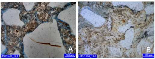
The identified thickness of the attacked region in the prepared slides corresponds to 1.6 mm to 4.1 mm for core 1 and 500 μm to 3.7 mm for core 2. Figure 5 shows the interface location between the attacked region (above) and the apparently unaffected region (bottom) for both cores. Note, in blue tones, the presence of microcracks and microporosity. The attacked region of both cores presents three zones of distinct alterations, namely:
 |
||||
| Figure 5. Interface location between the core regions (a) 1 and (b) 2. Simple polarization with capacitor. | ||||
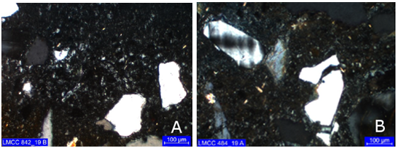
Primary zone (outermost): characterized by intense substitution of the paste by low birefringence crypt to microcrystalline material, possibly gypsum, with a texture like “mortar” (Figure 6). Core 1 also exhibit punctual presence of carbonation.
 |
||||
| Figure 6. First alteration layer, possibly gypsum cores (a) 1 and (b) 2. Cross polarization, with capacitor. | ||||
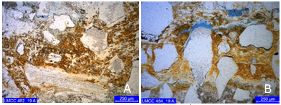
Secondary (intermediate) zone: shows partial replacement of the paste, with impregnation of iron hydroxides and possible organic matter (Figure 7). In the work Sun (2015), Fe enrichment, due to rust precipitation, was attributed as one of the causes of the presence of microcracks in the concrete alteration zones.
 |
||||
| Figure 7. Impregnation of iron hydroxides (reddish tones) from cores (a) 1 and (b) 3. Simple polarization with capacitor. | ||||
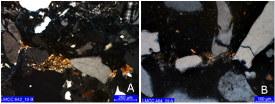
Tertiary zone: this is a discontinuous carbonation zone at the interface with the apparently unattacked concrete (Figure 8).
 |
||||
| Figure 8. Presence of carbonation (yellowish tones) at the interface between the attacked regions (top) and apparently not attacked (bottom) cores (a) 1 and (b) 2. Cross polarization with capacitor. | ||||
In both cores (Figure 9), the three zones show abundant microcracks, unfilled or partially filled by low birefringence crypt to microcrystalline material, gypsum.
 |
||||
| Figure 9. Microporosity zones in the paste associated with microcracks in blue tones (a) 1 and (b) 2. Simple polarization, with capacitor. | ||||
4.5 Scanning Electronic Microscopy - SEM
Microstructure analysis revealed considerable mineralogical changes on the attacked surface (Figure 10). Crystals of crystalline sulfoaluminosilicate phases were identified in the sample, containing Ca, Fe and K. In figure 10, the arrows point out to the locations of analysis by energy dispersive system (EDS - Figure 11).
 |
||||
| Figure 10. SEM scraped material - sulfoaluminosilicate crystalline phases, containing Ca, Fe and K. | ||||
In the micrograph of the scraped material, the presence of portlandite crystals was not identified, indicating that it has completely dissociated. Also, the acid has reduced the matrix to a more porous material, consisting of smaller particles.
 |
||||
| Figure 11. EDS spectra indicated in figure 10 (a) and (b) | ||||
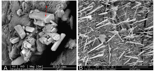
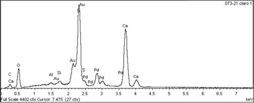
In the intermediate sample, two fragments of the light and dark portions were analyzed. In the lighter portion, crystals of rectangular morphology of hydrated calcium sulfate were identified (Figure 12.a), according to the EDS spectrum (Figure 13) with strong S and Ca signals, suggesting gypsum as the main component and ettringite crystals (Figure 12.b).
 |
||||
| Figure 12. SEM intermediate sample - fragments of the clear portion (a) hydrated calcium sulfate and (b) ettringite crystals. | ||||
 |
||||
| Figure 13. EDS spectra indicated in figure 12.a | ||||
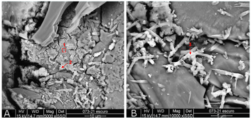
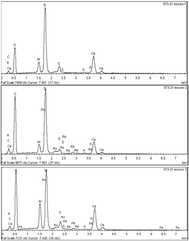
In the analyzed fragments of the darker portion of the intermediate sample, crystals of calcium aluminosilicate with sulfur or calcium sulfoaluminosilicate were identified (Figure 14).
 |
||||
| Figure 14. SEM intermediate sample - fragments of the dark portion calcium aluminosilicate crystals with sulfur or calcium sulfoaluminosilicate. | ||||
 |
||||
| Figure 15. EDS spectra indicated in figure 14 and b. | ||||
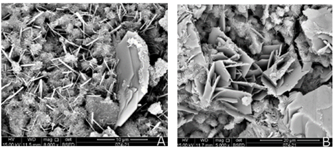
In the innermost sample, apparently not attacked, portlandite plates larger than 10μm can be observed with non-pathological ettringite needles in a C-S-H weave (Figure 16).
 |
||||
| Figure 16. SEM innermost sample - magnification of (a) 10µm and (b) 20µm. | ||||
4.6 X-Ray Diffraction - XRD
 |
||||
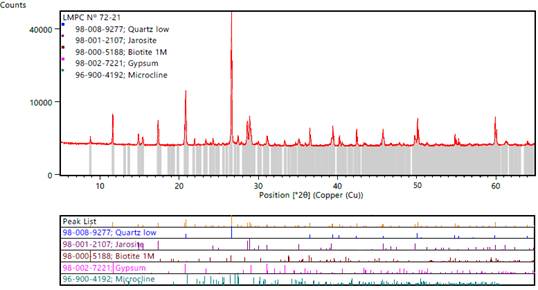
| Figure 17. X-Ray diffractogram - scraped material. | ||||
In the scraped sample (Figure 17) the presence of Jarosite and Gypsum was identified in a higher concentration. Similar results were found by Tazaki et.al., (1992) in severely corroded concrete pipes. According to the authors, under extremely low pH conditions, bacterial activity can break down Pyrite (iron disulfide, FeS₂) to form Jarosite. Usually, the main microorganisms involved in these reactions are identified as Thiobacillus ferrooxidans and/or Thiobacillus thiooxidans. In the study by Song et.al., (2020), when the acid attack reaches the surface of the steel bars, the corrosion process of the bars is accelerated by 퐇 ퟐ 퐒 forming iron sulfide, one of the compounds identified being FeS₂. Thus, it is possible that Jarosite formation comes from FeS₂, formed by the oxidation of the steel bars located in the attacked region. Gypsum was also identified as the most abundant compound on the concrete surface by authors such as Fernandes et.al., (2012), Davis et.al., (1998), Song, et. al., (2018) and Song et. al., (2020).
 |
||||
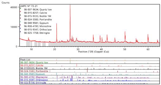
| Figure 18. X-ray diffractogram - intermediate sample. | ||||
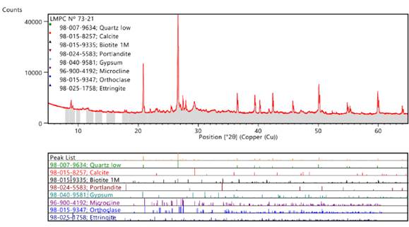
The results obtained by XRD confirm the presence of gypsum in the concrete in all analyzed layers. The presence of gypsum identified in the innermost layer (Figure 19), apparently not attacked, also indicates the beginning of degradation in this layer. From the intermediate sample, it is already possible to identify the presence of ettringite, probably due to a higher pH capable of guaranteeing the stability of that phase. The presence of calcite in the intermediate and innermost samples may come from the product of the carbonation reaction between calcium hydroxide and carbon dioxide.
 |
||||
| Figure 19. X-ray diffractogram - innermost sample. | ||||
4.7 Chemical determinations
The results obtained in the chemical determinations of the materials, expressed on the original basis and on the dry basis, are presented in Table 2.
| Table 2. Results of surface chemical determination | |||||||||||||||||||
| Visual quality (UNE 56544, 2011) | Amount of wooden beams | ||||||||||||||||||
|---|---|---|---|---|---|---|---|---|---|---|---|---|---|---|---|---|---|---|---|
| ME-1 | 4 | ||||||||||||||||||
| ME-2 | 7 | ||||||||||||||||||
| Rejected | 21 | ||||||||||||||||||
| NOTE - (*) The missing amount for 100% in the results of table 2 refers to undetermined water. It is emphasized that both results of the determinations are in the same calculation basis and, therefore, it was possible to determine the difference between them. | |||||||||||||||||||
The elements found in the water-soluble fraction are associated with the acidic gel formed from silicates, sulfates, sodium chlorides, potassium, magnesium, and calcium. The analyzed sample presented pH 2.8 at 19.8°C. This condition favors the colonization of acidophilic sulfur-oxidizing microorganisms (eg Acidithiobacillus Thiooxidans and Acidithiobacillus Ferrooxidans), which are associated with severe oxidation of steel (Wu et.al., 2020), justifying the steel bars corrosion/dissolution of 16 mm diameter. The pH result also justifies the absence of ettringite in the surface layer. Acidophilic microorganisms, in addition to oxidizing H 2 S in sulfuric acid, can oxidize thiosulfate and elemental sulfur that may be deposited on the concrete surface (Wells et.al., 2009).
As for the significant levels of elements found in the soluble fraction in nitric acid attack ( HNO 3 ) (insoluble in water, under the attack conditions proposed in the aforementioned test), they are associated with Jarosite [K2 Fe6 (OH)12 (SO4)4] and the possible presence of hisingerite [Fe3Si2O5OH4.2H2O], ferrous hydroxide [Fe OH2] and ferrous chloride [FeCl2 ]. According to Alexander and Fourie (2011), aluminum hydroxide [Al OH 3 ] and iron hydroxide [Fe OH 3 ] can precipitate in the layer after the dissolution of the aluminate and/or iron-aluminate phases depending on the concentration of hydrogen ion in the solution - precipitates iron hydroxide at a pH greater than 1.0 and aluminum hydroxide precipitates at a pH greater than 3.0.
The biogenic sulfuric acid causes the loss of concrete alkalinity that initially protects the steel bars, leading to reinforcement corrosion. The traditional corrosion of rebar is an electrochemical process that causes the dissolution of iron, forming various corrosion products, usually iron oxides, and hydroxides. However, as pointed out by Song et.al., (2020), when the biogenic sulfuric acid reaches the steel surface, the reactions and corrosion products can be different. In the authors' work, the main corrosion products of steel bars included iron oxides, iron oxyhydroxides, iron sulfides, iron chlorides, and iron sulfate.
Although iron-containing compounds are mostly formed from the dissolution of steel bars located in the attacked region, these compounds may also come from the dissolution of cement paste, since Portland cement contains about 3% Fe2 O3 (Jiang et.al., 2014). The formation of hisingerite, for example, may indicate the interaction of Fe, a product of corrosion of steel and/or cement paste, with Si from the dissolution of C-S-H.
5. Conclusions
From the inspection and results analysis of the Sewage Pumping Station the following conclusions can be drawn:
6. Acknowledgments
The authors would like to thank the Basic Sanitation Company of the State of São Paulo (SABESP) for allowing the availability of the structure analysis and for funding all the tests presented.
References
Associação Brasileira de Normas Técnicas. (2007). NBR 5739: Concreto - Ensaio de compressão de corpos-de-prova cilíndricos. Rio de Janeiro, Brasil.
Associação Brasileira de Normas Técnicas. (2007). NBR 7680: Concreto - Extração, preparo e ensaio de testemunhos de concreto. Rio de Janeiro, Brasil.
Associação Brasileira de Normas Técnicas. (2009). NBR 9917:2009 Agregados para concreto - Determinação de sais, cloretos e sulfatos solúveis. Rio de Janeiro, Brasil.
Associação Brasileira de Normas Técnicas. (1997). NBR 13810:1997 Água - Determinação de metais - Método de espectrometria de absorção atômica por chama. Rio de Janeiro, Brasil.
ASTM International. (2018). ASTM C114/2018 Standard Test Methods for Chemical Analysis of Hydraulic Cement.
ASTM International. (2017). ASTM C 856/2017 Standard Practice for Petrographic Examination of Hardened Concrete.
Alexander, M. G., Fourie, C. (2011), Performance of sewer pipe concrete mixtures with portland and calcium aluminate cements subject to mineral and biogenic acid attack. Materials and Structures, v. 44, pp. 313-330. DOI: 10.1617/s11527-010-9629-1
Davis, J. L., Nica D., Shields K., Roberts, D. J. (1998), Analysis of concrete from corroded sewer pipe. International Biodeterioration & Biodegradation, v. 42, pp. 75-84. DOI: https://doi.org/10.1016/S0964-8305(98)00049-3
Duchesne, J., Bertron, A. (2013), Leaching of cementitious materials by pure water and strong acids (HCl and HNO3). In: Performance of Cement-Based Materials in Aggressive Aqueous Environments: State-of-the-Art Report, RILEM TC 211 - PAE, 2013. DOI: https://doi.org/10.1007/978-94-007-5413-3_4
Eštokova, A., Harbul'áková, V. O., Luptáková, A., Števulová, N. (2012), Study of deterioration of concrete influenced by biogenic sulphate attack. Procedia Engineering, v. 42, pp. 1731-1738. DOI: https://doi.org/10.1016/j.proeng.2012.07.566.
Fernandes, I. et al. (2012), Identification of acid attack on concrete of a sewage system. Materials and Structures, v. 45, n. 3, p. 337-350. DOI: https://doi.org/10.1617/s11527-011-9769-y.
House, M. W., Weiss, W. J. (2014), Review of Microbially Induced Corrosion and Comments on Needs Related to Testing Procedures. Proceedings of the 4th International Conference on the Durability of Concrete Structures, pp. 94-103. DOI: https://doi.org/10.5703/1288284315388.
Jiang, G., Wightman, E., Donose, B., Yuan, Z., Bond, P., Keller, J. (2014), The role of iron in sulfide induced corrosion of sewer concrete. Water research. V.49. pp. 166-174. DOI: https://doi.org/10.1016/j.watres.2013.11.007.
Monteny, J., Vincke, E., Beeldens, A., De Belie, N., Taerwe, L., Van Gemert, D., Verstraete, W. (2000), Chemical, microbiological, and in situ test methods for biogenic sulfuric acid corrosion of concrete. Cement and Concrete Research, v. 30, pp. 623-634. DOI: https://doi.org/10.1016/S0008-8846(00)00219-2.
O’Connell, M., Mcnally, C., Richardson, M. (2010), Biochemical attack on concrete in wastewater applications: A state of the art review. Cement and Concrete Composites, v 32, p 479-485. DOI: https://doi.org/10.1016/j.cemconcomp.2010.05.001.
Scrivener, K., Belie, N. (2013), Bacteriogenic Sulfuric Acid Attack of Cementitious Materials in Sewage Systems. In: Performance of Cement-Based Materials in Aggressive Aqueous Environments, pp. 305-318. DOI: https://doi.org/10.1007/978-94-007-5413-312.
Song, Y., Tian, Y., Li, X., Wei, J., Zhang, H., Bond, P., Yuan, Z., Jiang, G. (2018), Distinct microbially induced concrete corrosion at the tidal region of reinforced concrete sewers. Water Research. 150. https://doi.org/10.1016/j.watres.2018.11.083.
Song, Y., Wightman, E., Kulandaivelu, J., Bu, H., Wang, Z., Yuan, Z., Jiang, G. (2020), Rebar corrosion and its interaction with concrete degradation in reinforced concrete sewers, Water Research. DOI: https://doi.org/10.1016/j.watres.2020.115961.
Song, Y., Chetty, K., Garbe, U., Wei, J., Bu, H., O’moore, L., Jiang, G. (2021), A novel granular sludge-based and highly corrosion-resistant bio-concrete in sewers. Science of The Total Environment, 791, 148270. doi: https://doi.org/10.1016/j.scitotenv.2021.148270.
Tazaki, K., Mori, T., Nonaka, T. (1992), Microbial jarosite and gypsum from corrosion of Portland Cement concrete. Canadian Mineralogist. v. 30, pp. 431-444.
Wells, T., Melchers, R. E., Bond, P. (2009), Factors involved in the long term corrosion of concrete sewers. In: Annual Conference of the Australasian Corrosion Association, 49th.
Wu, L., Hu, C., Liu, W.V. (2018), The Sustainability of Concrete in Sewer Tunnel-A Narrative Review of Acid Corrosion in the City of Edmonton, Canada. Sustainability. v. 10, 517. DOI: https://doi.org/10.3390/su10020517.
Wu, M., et al. (2020), Microbiologically induced corrosion of concrete in sewer structures: A review of the mechanisms and phenomena. Construction and Building Materials, v. 239. DOI: https://doi.org/10.1016/j.conbuildmat.2019.117813.
Yuan, H. (2013), Degradation modeling of concrete submitted to biogenic acid attack. Tese de Doutorado, Université Paris-Est. DOI: https://doi.org/10.1016/j.cemconres.2015.01.002.
