| Study Case | https://doi.org/10.21041/ra.v12i1.569 |
Practical use of the safety factor in the column repair strategy of a concrete building with historical value
Uso prático do fator de segurança na estratégia de reparo de pilar em um edifício de concreto com valor histórico Uso práctico del factor de seguridad en la estrategia de reparación de columnas de un edificio de concreto con valor histórico
J. A.
Briceño-Mena1
![]() ,
P.
Castro-Borges1
*
,
P.
Castro-Borges1
*
![]()
1 Departamento de Física Aplicada, Centro de Investigación y de Estudios Avanzados del Instituto Politécnico Nacional, Unidad Mérida, Mérida, Yucatán, México.
*Contact author: pcastro@cinvestav.mx
Reception:
November
09,
2021.
Acceptance:
December
21,
2021.
Publication: January 01, 2022
| Cite as: Briceño-Mena, J. A., Castro-Borges, P. (2022),“Practical use of thesafety factor in the column repair strategy of a concrete building with historical value”, Revista ALCONPAT, 12 (1), pp. 98 –109, DOI: https://doi.org/10.21041/ra.v12i1.569 |
Abstract
In this paper the practical use of the safety factor (FS) in the column repair strategy of a reinforced concrete building with historical value (almost 70 years) is presented. 80% of a building located in the historic center of the city of Campeche, Mexico, declared a World Heritage Site by UNESCO, was repaired. Strategies were used for a better use of material resources, equipment, and labor in the repair of walls, columns, slabs, and beams. One of the strategies was to use the theoretical FS to calculate the repair depth without structural consequences but fulfilling the purpose of controlling the carbonation of the concrete and maintaining the desired prediction of service life.
Keywords:
repair,
reinforced concrete,
durability,
security factor,
reparar,
concreto reforçado,
durabilidade,
fator de segurança,
reparación,
concreto reforzado,
durabilidad,
factor de seguridad
Resumo
Neste artigo discute-se o uso prático do fator de segurança (FS) na estratégia de reparo de pilares em um edifício de concreto armado com valor histórico (quase 70 anos). 80% de um prédio localizado no centro histórico da cidade de Campeche, no México, declarado Patrimônio da Humanidade pela UNESCO, foi reformado. Estratégias foram utilizadas para um melhor aproveitamento dos recursos materiais, equipamentos e mão de obra na reparação de paredes, pilares, lajes e vigas. Uma das estratégias foi utilizar o FS teórico para calcular a profundidade de reparo sem consequências estruturais, mas cumprindo o objetivo de controlar a carbonatação do concreto, e manter a previsão de vida útil desejada.
1. Introduction
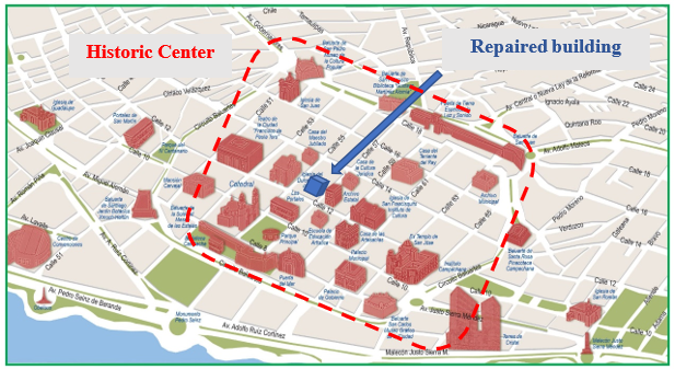
One of the common problems in concrete repairs is the misuse of structural specifications to know the depth to which they must be made, when faced with problems due to chlorides or carbonation. This results in a poorly optimized use of labor, equipment and materials that leads, not only to wrong repairs and the return of the problem, but also to a lack of sustainability in the entire process. This building with an internal space of more than 600 m2 and an approximate height of 20 m, and a frame-based structure, involved a demolition and subsequent construction of a new 4-level building. However, this plan was reconsidered because the building was approximately 70 years old and was located in the historic center of the city of San Francisco de Campeche, Campeche, Mexico (Figure 1), declared a World Heritage Site in 1999 by the United Nations Educational, Scientific and Cultural Organization (UNESCO). This place is protected by federal authorities such as the National Institute of Fine Arts and Literature (INBAL, in Spanish) and the National Institute of Anthropology and History (INAH, in Spanish). Therefore, rather than a demolition process, a repair strategy had to be considered that met the conditions established by the federal authorities, whereas much of the structure was preserved as possible (80%). For this reason, an extensive study was carried out on the durability of the property. Therefore, the parts that would remain standing prior to an intervention that would involve the repair and/or reinforcement of the different structural elements were defined, avoiding the initial demolition processes, and adapting it to the required conditions. It was proposed to attach a new internal structure to the building that has already been repaired, thus maintaining its exterior architecture, and rescuing interior areas.
 |
||||
| Figure 1. Location. of the structure within the protected area of Campeche | ||||
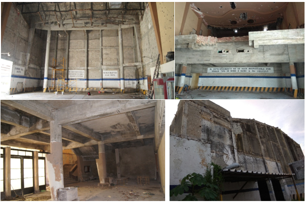
The structure had as its primary function that of being a cinema, later it functioned as a parking lot and was finally abandoned. These changes in use and abandonment were factors that potentiated the damage, as partially observed in the photos of Figure 2.
 |
||||
| Figure 2. State. of the structure before being repaired. | ||||
To develop an optimal repair, a structural analysis should be considered where the construction processes to be carried out during said intervention are considered since, during this process, loads can be added or removed due to the demolition of elements, vibrations, changes in the same properties of the repair materials, changes in resistance, shoring, among others (Ministerio de Vivienda y Urbanismo - Minvu, 2018; Allen, 1991). Therefore, it is important to establish the values with which it will work, such as the old and new resistance of the elements, safety factors, to name a few. In the present work it is illustrated, for the case of the columns, how the safety factor (SF) was used for the repair of the former Selem cinema.
1.1 The safety factor as a criterion for the durability of the repair
It was find in the literature the information about the Security Theory (González Cueto Vila and Quevedo Sotolongo, 2007) which, in general, consists of relating the security level (H) (equation 1), defined as H = 1- pf, where pf is the probability of failure. This level of security depends on all the variables that intervene in the design of the structure and how they can vary. The general equation that governs the theory of security is:
 |
Where: Hn is the safety level of the design.
H is the level of safety of the work.
In Civil Engineering, it can be understood as safety to prevent the structure from exceeding the permissible limit state, which is where it is considered that the structural behavior is acceptable (Ridell and Hidalgo, 2010). The SF is the one that relates the load or stress (C) to be applied to the structure with the maximum capacity (R) that it can withstand, that is, its maximum resistance.
 |
The SF is considered at the moment in which a structural element is being designed but it must also be considered when repairs are made since it has a direct relationship with the resistance of the material itself, as well as in the dimensions of the section of the elements. The SF is based on two coefficients (ACI 318-19, 2019), a coefficient of increased loads that consists of fictitiously increasing the load that will be applied to the structure when it is subjected to real loads during use. That is, multiplying the expected real load by a safety factor of increased load. The other coefficient is the reduction in the resistance of the material that makes up the element. The strength of the materials is reduced compared to the maximum allowable stresses. That is, dividing the resistance of the materials by a safety coefficient of reduction of resistance. Therefore, considering an element that in theory will have loads higher than the real ones and with a lower resistance than its own, there will be confidence in the security provided by the element even under very unfavorable conditions during its useful life.
Putting a practical fictitious example, the SF can be understood as follows: supposing that a column, which was designed to support 6 tons of load and 2 beams will rest on it, and each of these will transfer a load of 2 tons to the column. Therefore, it can be seen that the SF is 1.5 (SF = 6/4 = 1.5). Although in this example it was treated as a simple subject, in reality it is something much more complex. Various criteria must be considered, such as live loads (the people who will use the building), dead loads (furniture, for example), accidental loads, as well as environmental factors.
2. Methodology of the repair process
2.1 Damage inspection
Before carrying out any intervention in the structure, it was necessary to carry out an inspection of the damage, based on Mexican regulations (NMX-C-505-ONNCCE, 2016; NMX-C-520-ONNCCE, 2018), to establish the repair strategies. These inspections have already been published (Briceño-Mena et al, 2021) and can be consulted in the literature for more details. These inspections had 4 main axes:
2.2 Repair strategies
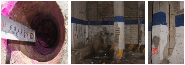
After the inspection carried out, it was found that the structural and architectural elements could be intervened for their consolidation with the new structure to be built inside the building as part of its change of use. All repair strategies were established to be able to provide the structure with a new service life and durability against current and future pathological problems to which it could be subjected, considering the mechanical characteristics of the elements themselves, as well as the use of the safety factors (NMX-C-530-ONNCCE, 2018; Val and Stewart, 2002; Melchers, 2001). These strategies were based on previous experiences and on the literature such as the Rehabilitar Manual (Helene and Pereira, 2003). The purpose of these repairs was to remove damaged concrete or that presented a pathological problem such as carbonation, as well as to ensure structural stability with the recalculation and restructuring of the amount of steel necessary in the elements, in addition to ensuring the adequate coating according to the structural requirements. Figure 3 shows processes of deterioration of the structure. To define the repair strategies, it was necessary to establish the types of repairs to be used:
 |
||||
| Figure 3. Carbonation and detachment of concrete. | ||||
2.2.1 Localized superficial repair (LSR)
This repair refers to those elements that present damage to the concrete with little depth and extension in relation to the dimensions of the structural element. Therefore, a repair was established in specific areas where cracks are observed at a depth no greater than 3 cm or before reaching the reinforcing steel.
2.2.2 Uniform superficial repair (USR)
This repair strategy is similar to the localized superficial repair since it will be carried out at a depth no greater than 3 cm, or before reaching the reinforcing steel, but contemplating the repair in a relatively large extension according to the dimensions of the structural element, delimiting for the works a maximum extension on the element of 1.5 m.
2.2.3 Localized deep repair (LDR)
This repair will be carried out in the structural elements where damage with a relatively small extension has been identified, with a depth greater than 3 cm, affecting the concrete behind the reinforcements.
2.2.4 Uniform deep repair (UDR)
As in the localized deep repair section, the repair is performed at a depth beyond the steel. However, as it was uniform, the repair was established in maximum sections of 1.5 m, due to structural issues.
3. Approach and use of the safety factor in repairs
The proposed repair techniques were carried out to apply strategies in the construction processes that allow avoiding unnecessary processes such as demolition, which would lead to the generation of rubble and garbage and even more so in important areas such as a world heritage site.
As an initial starting point to carry out the repair, it was important to analyze each element individually, its behavior, its maximum bearing load, its state, and later project it at a general level relating it to all the structural elements, thus obtaining a global behavior. In this way, it was possible to carry out the intervention considering all the possible factors of affectation and minimizing collateral damage of the repair process. This in turn leads to personnel training to prepare repairs since, at present, both workers and engineers are unaware of these issues, which causes an incorrect use of tools, materials, and equipment.
Although a repair strategy can be carried out by trained people, it is always important to consider safety and risk factors when working.
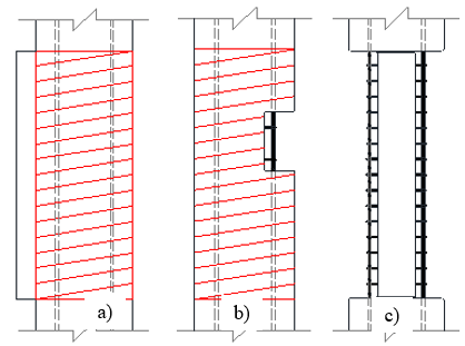
The SF theory was put into practice in the repair process of the structure described in this work. For this, the support of manuals, regulations, literature, and own experience was required to establish with the best criteria the ideal strategy per element. As previously mentioned, thanks to the previous inspection, the degree of damage was established and with it the repair strategy. Although 4 possible ones were established, in this work only what is related to uniform deep repair will be discussed (see Figure 4).
 |
||||
| Figure 4. Uniform deep repair: a) Delimitation of the area to be demolished, b) scarification started, c) final section after scarification | ||||
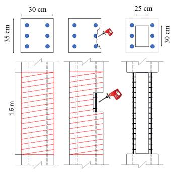
To carry out the repairs, it was necessary to establish the criteria with which they would be carried out. In the case of this structure, there were elements of different dimensions, for which universal repair criteria were established but they had to be verified before their execution. An UDR may or may not be large in relation to the size of the element. However, in this case and in order not to resort to materials, labor and time as is the case with the installation of stabilization struts, it was determined for practicality that the best thing was to carry out the repairs in sections of 1.5 linear meters. The following is an example of a rectangular type of column. The typical column (see Figure 5) had a cross section of 30x35 cm and with the help of the mechanical tests carried out it was possible to obtain the average compressive strength of the concrete, which is greater than 200 kg/cm2. Considering the cross section of the element and the minimum resistance obtained, it can be deduced that the column can support an axial load of 210,000 kg. Now, if the concrete in poor condition is scarified, and it is repaired beyond the reinforcement, remembering that the uniform deep repair is the one that occurs beyond 3 cm or behind the reinforcement, the new cross section of the element is 25x30 cm. If this new cross section is used and the compressive strength obtained previously with the extracted cylinders, it can be determined that the structure, even with the reduction in the concrete section, can support 150,000 kg. If it is considered that, at least, the element was designed with an SF of 1.5, then the structure was initially designed to carry a load of 140,000 kg safely. Therefore, even after scarifying, the item to be repaired can still withstand the loads exerted as it can resist up to 150,000 kg. This could not be entirely true since it is not an analysis that considers all the possible effects that may exist at the time of making the repairs. However, it is a good strategy to be carried out in the field since it allows a quick appreciation of how far one can intervene without structurally affecting the element and to be able to continue with the repair work once the diagnosis has been made.
 |
||||
| Figure 5. Criterion for delimitation and scarification of repairs | ||||
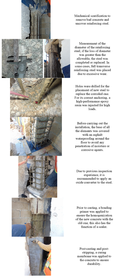
For the repair process, a guide was made which could be easily followed by the workers and which in turn was repeatable in various elements. This process can be seen in Figure 6. To carry out the repairs and in order to control various problems such as temperature contractions, modulus of elasticity, etc., it was decided to use some concrete with similar characteristics to carry out the repair of the elements.
 |
||||
| Figure 6. Uniform deep repair process | ||||
Naturally, the work of the workers involved on some occasion the breaking of the concrete cross section or going beyond the minimum section required according to the SF. In these cases, the precautions included not only punctual shoring, but also considering the monolithism of the structure when transferring the excess loads from the section contemplated to the neighboring elements.
With this work, it has been possible to demonstrate in a simple way the ease and confidence with which an UDR in columns can be approached, considering a simple calculation of the SF. Figure 7 shows a night view of the building already recovered.
 |
||||
| Figure 7. View of the intervention building | ||||
4. Conclusions
The purpose of this work was to present the practical case of repairing the columns of a 70-year-old reinforced concrete structure, which was in a state of abandonment and its total demolition had been planned. By mandate of the authorities, a durability study was carried out, which resulted in changing the demolition project to a repair one. To carry out this repair, it was necessary to consult different educational sources such as previous experiences that led to the creation of a practical manual for workers. This manual was based on durability criteria as well as design specifications that allow for safe operation. The SF played an important role in determining the redress mechanism, which resulted in significant savings in resources and time. With these repair procedures it is projected to have a durable structure that can fulfill the established service life with preventive maintenance.
5. Acknowledgments
The authors are grateful for the support of Coppel SA de CV, UACAM, Cinvestav, INAH and INBA. J.A. Briceño-Mena is grateful for the Conacyt doctoral scholarship.
References
American Concrete Institute (2019), ACI 318-19 Requisitos de Reglamento para Concreto Estructural. Primera impression: junio 2019. ISBN 978-1-64195-060-2
Allen, D. E. (1991), “Limit states criteria for structural evaluation of existing buildings” Canadian Journal of Civil Engineering, vol. 18, no. 6, pp. 995-1004, doi: https://doi.org/10.1139/l91-122
Briceño-Mena, J. A., Balancán-Zapata, M. G., Castro-Borges, P., Pérez-López, T. (2021), “Extending the Service Life of a Historical Concrete Building”, Materials Performance, pp. 1-8, 2021. URL: https://materialsperformance.com/articles/coating-linings/2021/04/extending-the-service-life-of-a-historical-concrete-building
González Cueto Vila, A. V., Quevedo Sotolongo, G. (2007), “Aplicación de la teoría de seguridad al diseño de cimentaciones en arenas. Chequeo de linealidad” Revista Ingeniería de Construcción Vol. 22 No. 2, pp. 81-88, www.ing.puc.cl/ricvol. https://scielo.conicyt.cl/pdf/ric/v22n2/art02.pdf
Ridell C. R., Hidalgo O. P. (2010), Diseño Estructural, Quinta. Pontificia Universidad Católica de Chile. I.S.B.N. 956-14-0463-X
Helene, P., Pereira, F. (2003), Manual de rehabilitación de estructuras de hormigón - reparación, refuerzo y protección. Red Rehabilitar, Ciencia y Tecnología para el Desarrollo (CYTED), 2003.
Ministerio de Vivienda y Urbanismo - Minvu (2018), Vol. 4. Manual De Reparaciones Y Refuerzos Estructurales. Editor: División Técnica de Estudio y Fomento Habitacional - Ditec, Minvu, ISBN: 978-956-9432-85-9. Gobierno de Chile, febrero de 2018.
Melchers, R. E. (2001), “Assessment of existing structures-approaches and research needs” J. Struct. Eng., vol. 127, no. 4, pp. 406-411, doi: https://doi.org/10.1061/(ASCE)0733-9445(2001)127:4(406)
Organismo Nacional de Normalización y Certificación de la Construcción y Edificación S. C. (2016) NMX-C-505-ONNCCE, Industria de la Construcción - Inspección Preliminar de Daños en Estructuras de Concreto Hidráulico con Criterios de Durabilidad - Procedimientos.
Organismo Nacional de Normalización y Certificación de la Construcción y Edificación S. C. (2018), NMX-C-520-ONNCCE, Industria de la Construcción-Inspección Detallada de Daños en Estructuras de Concreto Hidráulico con Criterios de Durabilidad-Procedimientos.
Organismo Nacional de Normalización y Certificación de la Construcción y Edificación S. C. (2018) NMX-C-530-ONNCCE, Industria de la construcción - Durabilidad - Norma general de durabilidad de estructuras de concreto reforzado - Criterios y Especificaciones.
Val, D. V., Stewart, M. G. (2002), “Safety Factors for Assessment of Existing Structures,” J. Struct. Eng., vol. 128, no. 2, pp. 258-265, doi: https://doi.org/10.1061/(ASCE)0733-9445(2002)128:2(258)
