
| Basic Research | https://doi.org/10.21041/ra.v11i3.548 |
Theoretical-experimental behavior of steel fibers as a partial replacement for shear reinforcement in reinforced concrete beams
Comportamento teórico-experimental de fibras de aço em substituição parcial à armadura de cisalhamento em vigas de concreto armado
Comportamiento teórico-experimental de fibras de acero como reemplazo parcial del refuerzo a cortante en vigas de concreto reforzado
C. A.
Juárez-Alvarado1
![]() ,
J. M.
Mendoza-Rangel1
*
,
J. M.
Mendoza-Rangel1
*
![]() ,
B. T.
Terán-Torres1
,
B. T.
Terán-Torres1
![]() ,
P. L.
Valdez-Tamez1
,
P. L.
Valdez-Tamez1
![]() , G. Castruita-Velázquez1
, G. Castruita-Velázquez1
1 Universidad Autónoma de Nuevo León, Facultad de Ingeniería Civil, Av. Universidad S/N, Cd. Universitaria, San Nicolás de los Garza, Nuevo León, México.
*Contact author: jose.mendozarn@uanl.edu.mx
Reception: July 16, 2021.
Acceptance: August 13, 2021.
Publication: September 01, 2021.
| Cite as: Juárez-Alvarado, C. A., Mendoza-Rangel, J. M., Terán-Torres, B. T., Valdez-Tamez, P. L., Castruita-Velázquez, G. (2021), "Theoretical-experimental behavior of steel fibers as a partial replacement for shear reinforcement in reinforced concrete beams", Revista ALCONPAT, 11 (3), pp. 31 – 41, DOI: https://doi.org/10.21041/ra.v11i3.548 |
Abstract
It is proposed to partially replace the stirrups with steel fibers and thus improve the shear strength of concrete beams. The variables studied were: water/cement ratios (w/c) = 0.55 and 0.35, and fiber volume (Vf) = 0, 0.3, 0.5, 0.7% and 0, 0.2, 0.4, 0.6% respectively, along with the separation of the stirrups. The results showed that the shear strength of the reinforced fiber and stirrups was greater than the strength of the beams reinforced only with stirrups. Experimental data and the strength prediction models comparison showed that the analytical models adequately predict the effect of the w/c ratio, the Vf, and the contribution of longitudinal and transverse steel. Also, the studied models predicted mainly conservative values with respect to the ultimate shear strength.
Keywords:Fiber-reinforced concrete, beams, shear strength, analytical model, stirrups, steel fibers.
Resumo
Propõe-se a substituição parcial dos estribos por fibras de aço para melhorar a resistência ao cisalhamento das vigas. Como variáveis: relação (a/c) = 0,55 e 0,35 com (Vf) = 0, 0,3, 0,5, 0,7% e 0, 0,2, 0,4, 0,6% respectivamente e espaçamento de estribo. Os resultados mostraram que a resistência ao cisalhamento com reforço de estribos e fibras foi maior que a das vigas controle com estribos separados (d/2). A comparação entre os dados experimentais e os modelos de predição de resistência mostrou que o efeito da relação (a/c), (Vf), a contribuição do aço longitudinal e a presença de estribos está adequadamente previsto. Os modelos estudados previram, na maioria dos casos, valores conservadores para a resistência última ao cisalhamento experimental.
Palavras-chave:
concreto reforçado com fibras,
vigas,
tensão de cisalhamento,
modelo analítico,
estribos,
fibras de aço.
Resumen
Se propone sustituir parcialmente estribos por fibras de acero para mejorar la resistencia a cortante de vigas. Las variables estudiadas fueron: la relación agua/cemento (a/c) = 0.55 y 0.35, y el volumen de fibra (Vf) = 0, 0.3, 0.5, 0.7% y 0, 0.2, 0.4, 0.6% respectivamente, y la separación de estribos. Los resultados mostraron que la resistencia a cortante con estribos y fibras, fue mayor que la resistencia de las vigas reforzadas con solo estribos. La comparativa entre los datos experimentales y modelos analíticos de predicción de resistencia, mostró que se predice adecuadamente el efecto de la relación (a/c), el Vf, y la aportación del acero longitudinal y transversal. Además, los modelos estudiados predijeron mayormente valores conservadores para la resistencia ultima experimental a cortante.
Palabras clave:
concreto fibroreforzado,
vigas,
esfuerzo a cortante,
modelo analítico,
estribos,
fibras de acero.
1. Introduction
In most reinforced concrete structures, straight corrugated rebars are usually employed, which are proposed in zones subjected to tension in the structural elements to resist normal stresses produced by the shear force and bending moment (V, M). However, when such forces exceed the admissible stresses, diagonal tensile cracks are developed with an inclined orientation due to the shear force. If the concrete is unable to withstand such actions, transverse reinforcement is proposed to reduce the cracking due to shear force (Khuntia et al, 2001).
The failures shown in the structural elements are of great interest due to the risk that they pose to the final users, and one of the most concerning failures is the diagonal tension shear, which presents itself in a fragile form, i.e., there is no warning prior collapse. These failures can be produced by external events, such as seismic forces or impact due to accidental loading.
To counter this type of failure, the structures are reinforced with transverse rebars (stirrups) which, depending on the loads acting on the structure, can become close enough in the zone. This will prevent concrete to flow freely between the steel rebars, causing segregation and weakness in such areas of the structure. One alternative to solve this problem is the use of steel fibers, which provide higher strength to bending moment, impact, cracking, and lower permeability (Shin et al, 1994). The use of steel fibers comes from the basic idea of strengthening the concrete matrix under tensile stresses. The distribution of the fibers as a group with the concrete leads to better behavior since they reduce the fragile nature of the element. As a consequence of the use of the steel fibers, a larger toughness capacity is presented in the composite material since they can absorb energy before reaching the failure of the element and its collapse. The addition of the steel fibers in the concrete helps to transform its fragile characteristic into a ductile one. This is due to the fact that fibers are distributed uniformly and oriented randomly in all directions in the concrete mass (Ashour et al, 1992).
In general, the reinforced concrete elements are designed to resist external loads which produce stresses and displacement of different types, these designs are usually based on construction codes and on technical literature which presents well-established procedures for most structures. Nevertheless, when the reinforcement of the concrete differs from the conventional steel rebars, these procedures and theories must account for the contribution of this additional reinforcement. In most of the technical literature, there is a lack of design procedures for concrete structures that are reinforced with steel fibers, which in contrast, there is plenty of research that shows that steel fibers provide ductility and an increase in the mechanical tensile strength of the concrete (Juárez, et al., 2007). Hence, by taking into consideration the main contribution that steel fibers have, it is convenient to direct such studies towards the behavior under shear stresses in fiber-reinforced concrete beams; this stress is also known as diagonal tensile stress, which is located in the support zones of the beam (Park et al., 1990).
The shear stress leads to sudden failure if the transverse reinforcement in the concrete (stirrups) is not enough, and this failure is usually presented under a lesser load than that for the bending failure. Therefore, if one considers utilizing steel fibers as alternative reinforcement for shear to prevent the sudden failure and increase the ultimate strength, it will be convenient to present theoretical procedures to predict such strength and, by comparing with experimental data, one will be able to identify the contribution of the fiber and hence finding a reliable aid for design. There are several studies that account for this contribution of the steel fibers, Jun et al. (2018) observed that the fiber and the stirrup increase the stiffness, by decreasing the deflection under ultimate load, however, the effect of the fibers decreased with the increment of the amount of stirrups. In addition, it was found out that fiber reduces the strain in the stirrup and the diagonal cracking, due to a bridging of the crack. On the other hand, one of the most recent studies that model the shear was developed by (Mari Bernat et al. 2020), which proposed a multi-action model based on the establishment of equilibrium equations that include the mechanisms of shear strength that the fibers provide in concrete beams without stirrups.
By considering the aforementioned, a viable and practical solution to this problem, with reinforcement inside the matrix, with the steel fiber addition in the concrete mass, and hence to be able to increase the separation of the stirrups and obtaining a better distribution of the concrete is proposed in this research. This research work proposes the partial substitution of the stirrups by the steel fibers and with that the improve or maintain the mechanical shear strength under diagonal tension of the concrete structures.
The results obtained experimentally showed that the diagonal shear strength of the fiber-reinforced beams, with stirrups, is substantially larger than that estimated by the ACI-318 code. In addition, theoretical procedures to predict the shear strength in fiber-reinforced concrete beams were evaluated, through the comparison of two mathematical models obtained from the literature review (Swamy et al., 1993 and Narayanan et al., 1987), and the experimental data of the 20 beams tested under diagonal tensile shear. It was found out that the two models predict adequately the effect of the w/c ratio, the volume fiber (Vf), the contribution of the longitudinal steel, and the presence of the stirrup under shear ultimate strength. The models of Swamy and Narayanan predicted conservative values with respect to the ultimate shear strength, approaching the reached value of the experimental shear strength.
2. Experimental methodology
2.1 Materials
Cement Portland type CPC 30R was used, which satisfies the standard NMX-C-414-ONNCCE-2017, coarse aggregate with a maximum size of 12.7 mm and 4.75 mm for the fine aggregate, which meet the standard ASTM C33-18, the aggregates were of limestone typical of the Monterrey area, with a relative density of 2.59 and 2.71 and with an absorption percentage of 0.72 and 1.82 for each aggregate, respectively. The additive used was a water reducer hyperfludifier polycarboxylate based, with a liquid content of 56%, mass of 44%, and a density of 1.11 g/cm3. The longitudinal steel reinforcements were four rebars No. 5 (16mm) with fy=420 MPa and for the stirrups, rebars No. 2 (6.4 mm) were used with fy = 280 MPa (ASTM A615-20). Steel fibers were used with 50 mm of length and 1 mm of average thickness, with an aspect ratio of 50, fy = 1,152 MPa, fiber “Deformed Slit Sheet” type, according to ASTM A820-16 standard.
2.2 Mixtures composition
In tables 1 and 2, different mixtures of the concrete studied are shown. A total of 8 mixtures were fabricated, four for the ratio w/c = 0.55 and the other four for the ratio w/c = 0.35. In both cases, the variables were: the percentage of fibers volume per cubic meter of concrete and the transverse shear reinforcement using closed-loop stirrups. The beams were fabricated in duplicate for each mixture and each variable.
| Table 1. Mixture composition for strength of f´c = 25 MPa, in kg/m3. | ||||||||||||||
| Materials | % of steel fiber | |||||||||||||
|---|---|---|---|---|---|---|---|---|---|---|---|---|---|---|
| 0.0 | 0.3 | 0.5 | 0.7 | |||||||||||
| w/c = 0.55 | ||||||||||||||
| Total water | 157 | 157 | 157 | 157 | ||||||||||
| Cement | 280 | 280 | 280 | 280 | ||||||||||
| Coarse A. | 792 | 782.6 | 766.9 | 770.1 | ||||||||||
| Fine A. | 1139 | 1124.8 | 1115.5 | 1106.1 | ||||||||||
| Fiber | 0 | 23.5 | 39.2 | 54.8 | ||||||||||
| Additive | 1.1 | 1.4 | 1.6 | 2.2 | ||||||||||
| Air % | 2.5 | 2.5 | 2.5 | 2.5 | ||||||||||
| Table 2. Mixture composition for strength of f´c = 35 MPa, in kg/m3. | ||||||||||||||
| Materials | % of steel fiber | |||||||||||||
|---|---|---|---|---|---|---|---|---|---|---|---|---|---|---|
| 0.0 | 0.2 | 0.4 | 0.6 | |||||||||||
| w/c = 0.35 | ||||||||||||||
| Total water | 136 | 136 | 136 | 136 | ||||||||||
| Cement | 380 | 380 | 380 | 380 | ||||||||||
| Coarse A. | 761 | 753.9 | 748.5 | 742.2 | ||||||||||
| Fine A. | 1139 | 1128.4 | 1120.2 | 1110.8 | ||||||||||
| Fiber | 0 | 17.7 | 31.3 | 47 | ||||||||||
| Additive | 1.9 | 2.3 | 2.7 | 3.4 | ||||||||||
| Air % | 2.5 | 2.5 | 2.5 | 2.5 | ||||||||||
| Total water = Reaction water + absorption water + additive water | ||||||||||||||
2.3 Mixing, casting, and curing
The mixtures were fabricated in a concrete mixer with a reversing drum with a capacity of 90 L. The coarse and fine aggregates were homogenized during a minute, with a third of the water of reaction + absorption, afterwards, the cement was added, along with the additive and the remaining water of reaction by mixing for three minutes, then by allowing it to rest for three minutes and by mixing again for two more minutes. When the fibers were required, these were added during the second period of mixing. After the mixing, the consistency was measured through the concrete slump test and the air content according to the standards ASTM C143-20 and ASTM C231-17a, respectively, but only for the mixtures without fibers. The compressive strength was performed by means of the test of six cylinders of the fiber-reinforced concrete of 100 mm of diameter and 200 mm of height, fabricated with each fiber percentage, standardly cured according to the standard ASTM C192-19, and tested at 28 days according to the testing method in ASTM C39-21. In addition, the tensile strength was obtained through diagonal tensile strength test, using six cylinders of 150 mm of diameter and 300 mm of height, cured for 28 days, and tested according to the method ASTM C496-17. On the other hand, the concrete of the beams was poured into metallic falsework, compacted with an electric internal vibrator, which allowed to homogenize the fibers in the concrete mixture, with no agglomeration of them observed. All beams were cured with a water layer inside the falsework up to the age of 7 days, afterwards, they were cured with curing membrane water-based formulated with acrylic spread resins, until the moment of the experiment.
2.4 Fabrication and testing of fiber-reinforced beams
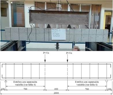
Twenty reinforced concrete beams of 2000x150x250 mm were fabricated, from which, 10 beams were casted with concrete mixture with a water/cement ratio (w/c) = 0.55, to obtain a concrete strength specified of f´c=25 MPa, and the remaining 10 beams were casted with the concrete mixture with a ratio w/a = 0.35 for a compressive strength specified of f´c=35 MPa. The beams were fabricated in duplicate, por each w/c ratio, eight pairs of beams with stirrups, and two pairs of beams without stirrups (see table 3). To evaluate the effect of the fibers with the shear reinforcement in the concrete matrix, steel fibers were added with 50 mm of length and 1 mm of average thickness. Beams were fabricated in duplicate, reinforced with closed-loop stirrup and with the following fiber percentage with respect the total volume of the mixture: 0% (control), 0.3%, 0.5%, 0.7% for the ratio w/c = 0.55. In a similar manner, 0% (control), 0.2%, 0.4%, 0.6% for the ratio w/c = 0.35. To obtain the same separation of stirrups for both ratios w/c, as observed in table 3, the percentage of fibers must be different, being smaller for the concrete with larger compressive strength. In addition, two pairs of beams were fabricated without stirrups but with the larger percentage of fibers of 0.7% and 0.6% for the ratios w/c = 0.55 and 0.35, respectively. The transverse steel reinforcement detailing of the beams and the position for load application can be observed in figure 1. The location of the loads for the test was determined following the criterion used by Park et al., 1990, to define a shear span, which allows to produce high shear forces for diagonal tension at the ends of the beams. All beams were tested at the age of 28 days.
| Table 3. Details of the reinforcement of stirrups and fibers of the beams. | ||||||||||||||
| w/c = 0.55 | Separation of stirrups, mm | 150 | 250 | 300 | 350 | S/E | ||||||||
| Percentage of fiber, % | 0.0 | 0.3 | 0.5 | 0.7 | 0.7 | |||||||||
| Number of specimens | 2 | 2 | 2 | 2 | 2 | |||||||||
| w/c= 0.35 | Separation of stirrups, mm | 150 | 250 | 300 | 350 | S/E | ||||||||
| Percentage of fiber, % | 0.0 | 0.2 | 0.4 | 0.6 | 0.6 | |||||||||
| Number of specimens | 2 | 2 | 2 | 2 | 2 | |||||||||
| * Nomenclature: S/E = without stirrups | ||||||||||||||
 |
||||
| Figure 1. General detailing of the tested beams | ||||
In table 4, it is established the designation used for the 20 beams fabricated, along with the amount and distribution of longitudinal reinforcement and the transverse shear reinforcement (stirrups), and the percentage of steel fibers used.
| Table 4. Identification of the fiber-reinforced beams | ||||||||||||||
| Designation | Concrete strength f´c, MPa | w/c Ratio | Longitudinal reinforcement Ф 16 mm | Transverse Reinforcement Ф 6.4 mm | Steel fibers, % | |||||||||
|---|---|---|---|---|---|---|---|---|---|---|---|---|---|---|
| Mva-N-1,0.0 | 25 | 0.55 | 4 rebars | 12 stirrups @ 150 mm | 0.0 | |||||||||
| Mva-N-2,0.0 | ||||||||||||||
| Mva-N-3,0.3 | 8 stirrups @ 250 mm | 0.3 | ||||||||||||
| Mva-N-4,0.3 | ||||||||||||||
| Mva-N-5,0.5 | 8 stirrups @ 300 mm | 0.5 | ||||||||||||
| Mva-N-6,0.5 | ||||||||||||||
| Mva-N-7,0.7 | 6 stirrups @ 350 mm | 0.7 | ||||||||||||
| Mva-N-8,0.7 | ||||||||||||||
| Mvb-N-9,0.0 | 35 | 0.35 | 12 stirrups @ 150 mm | 0.0 | ||||||||||
| Mvb-N-10,0.0 | ||||||||||||||
| Mvb-N-11,0.2 | 8 stirrups @ 250 mm | 0.2 | ||||||||||||
| Mvb-N-12,0.2 | ||||||||||||||
| Mvb-N-13,0.4 | 8 stirrups @ 300 mm | 0.4 | ||||||||||||
| Mvb-N-14,0.4 | ||||||||||||||
| Mvb-N-15,0.6 | 6 stirrups @ 350 mm | 0.6 | ||||||||||||
| Mvb-N-16,0.6 | ||||||||||||||
| Mva-N-17,0.7 | 25 | 0.55 | Without stirrups | 0.7 | ||||||||||
| Mva-N-18,0.7 | ||||||||||||||
| Mvb-N-19,0.6 | 35 | 0.35 | Without stirrups | 0.6 | ||||||||||
| Mvb-N-20,0.6 | ||||||||||||||
| Nomenclature: Mva: Beam with f´c = 25 MPa Mvb: Beam with f´c = 35 MPa N-1, 2...20: Numeration of the beams 0.0, 0.2, ...0.7: % of fibers with respect to the concrete volume | ||||||||||||||
3. Analytical model for concrete without fibers
3.1 Model proposed by the Committee 318 of the American Concrete Institute (ACI 318-14)
The nominal shear strength of a transverse section of a reinforced concrete beam is obtained according to the following equation:
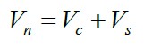 |
(1) |
For beams subjected to diagonal tensile shear only, the shear strength provided by the concrete is the following:
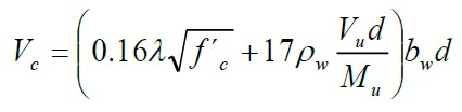 |
(2) |
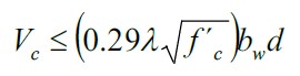 |
(3) |
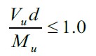 |
(4) |
 |
(5) |
In addition, the shear strength provided by the stirrups is given in the following manner:
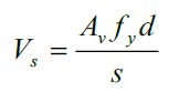 |
(6) |
Nomenclature:
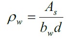
bw = Width of the beam (mm).
d = Effective depth of the beam (mm).
f´c = Compressive design strength given at the age of 28 days. (MPa).
fy = Yield strength of the stirrups (MPa).
S = Separation of stirrups (mm).
As = Area of the longitudinal steel (mm2).
Av = Area of the stirrups (mm2).
Mu = Ultimate acting moment (kN-mm).
Vc = Shear strength provided by the concrete (kN).
Vn = Theoretical nominal shear strength (kN).
Vs = Shear strength provided by the stirrups (kN).
Vu = Ultimate acting shear force (kN).
ρw = Longitudinal reinforcement ratio in the web
λ = Density factor of the concrete = 1.0 for regular weight concrete.
4. Classical analytical methods for fiber-reinforced concrete
4.1 Swamy model (Swamy et al., 1974)
This model is characterized for being a simple method, it considers that the ultimate theoretical shear strength of a fiber-reinforced beam without stirrups is determined in the following manner:
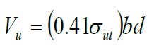 |
(7) |
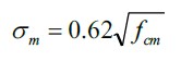
The approach of the Swamy model was developed to determine the ultimate tensile strength of the fiber-reinforced concrete under bending moment, with the objective to avoid carrying out several tests in the laboratory to determine this result, hence the model proposes the following equation:
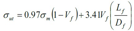 |
(8) |
 |
(9) |
In the case of the presence of stirrups in the beam, the contribution to the ultimate shear strength obtained from equation (13) is calculated through the following equation:
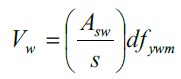 |
(10) |
Nomenclature:
b = Width of the beam (mm).
d = Effective depth of the beam (mm).
fcm = Compressive strength of fiber-reinforced concrete (MPa).
fywm = Yield strength of the stirrups (MPa).
s = Separation of the stirrups (mm).
Asw = Area of the stirrups (mm2).
Df = Diameter of the fiber (mm).
Lf = Length of the fiber (mm).
Vf = Volume fraction of fibers.
Vw = Shear strength provided by the stirrups (kN).
Vu = Ultimate theoretical shear strength (kN).
σm = Tensile strength of the fiber-reinforced concrete (MPa).
σut = Ultimate tensile strength of the fiber-reinforced concrete under bending moment (MPa).
4.2 Narayanan Model (Narayanan et al., 1987)
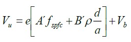
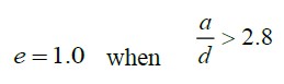
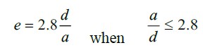
This model considers three terms for the computation of the ultimate theoretical shear strength, the first term accounts for the contribution of the fiber reinforcing the concrete, the second term considers the dowel action that provides the longitudinal reinforcement, and the last term proposes the contribution of the strength due to extraction of the fibers during the diagonal cracking. In this manner, the proposed model is the following:
 |
(11) |
 |
(12) |
 |
(13) |
 |
(14) |
 |
(15) |
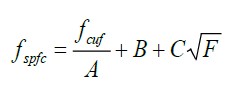
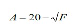
The identified factors that influence the strength of the fiber-reinforced concrete are the volume fraction of the fiber, the aspect ratio, and the interface that exist between the fiber and the matrix. The next equation considers these three factors:
 |
(16) |
 |
(17) |
 |
(18) |
Nomenclature:
a = Shear span (mm).
b = Width of the beam (mm).
d = Effective depth of the beam (mm).
df = Adherence factor depending on the type of fiber = 0.5 circulars; 0.75 waved; 1 indented.
e = Adimensional factor which accounts for the dowel effect action.
fcuf = Compressive strength of the fiber-reinforced concrete (MPa).
fspfc = Diametral tensile strength of the fiber-reinforced concrete (MPa).
A = Adimensional constant.
A´ = Adimensional constant = 0.24
As = Area of the longitudinal reinfocement (mm2).
B = Constant = 0.7 MPa
B´ = Constant = 80 MPa
C = Constant = 1 MPa
F = Fiber factor.
Vb = Force of extraction of the fiber during cracking (kN).
Vu = Ultimate theoretical shear strength (kN).
ρf = Volume fraction of fibers.
ρ = Longitudinal reinforcement ratio.
τ = Ultimate adherence strength = 4.15 MPa
5. Results and discussion
5.1 Prediction of the ultimate strength using the analytical models.
In table 5 the results on the nominal shear strength (Vn) are presented, which are obtained through ACI 318-14 models with equations (1), (2), and (6). The strength Vn is used in the design of reinforced concrete beams under shear force, and it includes the strength provided by the concrete, the longitudinal reinforcement, and the stirrups. This model does not consider the contribution of the fibers as concrete reinforcement.
| Table 5. Nominal shear strength in concrete beams without fibers, with stirrups equation (1) and without stirrups equation (2) for both w/c ratios | ||||||||||||||
| Ratio w/c | f´c MPa | Vc (eq. 2) kN | fy MPa | Vs kN | Vn (eq.1) kN | |||||||||
|---|---|---|---|---|---|---|---|---|---|---|---|---|---|---|
| 0.55 | 25 | 39.5 | 280 | 25.8 | 65.3 | |||||||||
| 0.35 | 35 | 44.2 | 280 | 25.8 | 70.0 | |||||||||
There are previous studies that propose analytical models based on experimental results (Dinh et al., 2010, Aoude et al., 2012), and others that analyze experimental data coming from diverse sources and use an important number of analytical models for comparison, (Haisam, 2011). The objective of the herein study was to produce its own scientific experiment, which validates the analytical models selected, which are considered as classical in the literature since they have been the foundation of many others, with the merit of the latter based on the personalization of a variable without a substantial modification to the original model.
In table 6, the experimental results of the compressive and tensile strengths of the fiber-reinforced concrete are presented, which were used in the analytical models for the prediction of the ultimate theoretical shear strength. The compressive strengths were taken as fcuf for Narayanan model. In the same manner, the tensile strength was considered as fspfc for Narayanan model. These values were obtained in a standardized manner as previously indicated, hence, there was no significant difficulty in their determination for the application of the models studied.
| Table 6. Compressive and tensile strength of the fiber-reinforced concrete specimens at the age of 28 days | ||||||||||||||
| Designation | Compressive strength MPa | Tensile strength MPa | Designation | Compresive strength MPa | Tensile strength MPa | |||||||||
|---|---|---|---|---|---|---|---|---|---|---|---|---|---|---|
| Mva-N-1,0.0 | 28.5 | 2.5 | Mvb-N-9,0.0 | 44.9 | 3.4 | |||||||||
| Mva-N-2,0.0 | 31.2 | 2.7 | Mvb-N-10,0.0 | 46.4 | 3.8 | |||||||||
| Mva-N-3,0.3 | 29.5 | 3.2 | Mvb-N-11,0.2 | 50.1 | 3.8 | |||||||||
| Mva-N-4,0.3 | 29.6 | 2.5 | Mvb-N-12,0.2 | 37.2 | 3.4 | |||||||||
| Mva-N-5,0.5 | 30.2 | 3.2 | Mvb-N-13,0.4 | 45.8 | 3.5 | |||||||||
| Mva-N-6,0.5 | 31.9 | 3.4 | Mvb-N-14,0.4 | 51.7 | 3.7 | |||||||||
| Mva-N-7,0.7 | 31.5 | 3.2 | Mvb-N-15,0.6 | 48.2 | 4.2 | |||||||||
| Mva-N-8,0.7 | 32.7 | 3.6 | Mvb-N-16,0.6 | 46.1 | 3.9 | |||||||||
In table 7, the results obtained from the selected analytical models are presented, to determine the ultimate theoretical shear strength
| Table 7. Ultimate theoretical shear strength of fiber-reinforced beams for both w/c ratios. | ||||||||||||||
| Designation | Swamy Model kN | Narayanan Model kN | Designation | Swamy Model kN | Narayanan Model kN | |||||||||
|---|---|---|---|---|---|---|---|---|---|---|---|---|---|---|
| Mva-N-1,0.0 | - | - | Mvb-N-11,0.2 | 75.0 | 76.5 | |||||||||
| Mva-N-2,0.0 | - | - | Mvb-N-12,0.2 | 75.0 | 76.5 | |||||||||
| Mva-N-3,0.3 | 68.2 | 70.6 | Mvb-N-13,0.4 | 72.9 | 75.5 | |||||||||
| Mva-N-4,0.3 | 68.2 | 70.6 | Mvb-N-14,0.4 | 72.9 | 75.5 | |||||||||
| Mva-N-5,0.5 | 66.1 | 69.9 | Mvb-N-15,0.6 | 71.4 | 76.6 | |||||||||
| Mva-N-6,0.5 | 66.1 | 69.9 | Mvb-N-16,0.6 | 71.4 | 76.6 | |||||||||
| Mva-N-7,0.7 | 64.7 | 69.9 | Mva-N-17,0.7 | 53.6 | 58.9 | |||||||||
| Mva-N-8,0.7 | 64.7 | 69.9 | Mva-N-18,0.7 | 53.6 | 58.9 | |||||||||
| Mvb-N-9,0.0 | - | - | Mvb-N-19,0.6 | 60.4 | 64.6 | |||||||||
| Mvb-N-10,0.0 | - | - | Mvb-N-20,0.6 | 60.4 | 64.6 | |||||||||
5.2 Effect of the reinforcement with fibers in reinforced concrete beams with respect to the theoretical models.
Table 8 shows the experimental results of the shear strength of the fiber-reinforced concrete beams with and without stirrups, it also shows the average for each pair of tested beams in the laboratory.
| Table 8. Experimental shear strength of fiber-reinforced concrete beams, for both w/c ratios. | ||||||||||||||
| Designation | Vuexp kN | Average kN | Designation | Vuexp kN | Average kN | |||||||||
|---|---|---|---|---|---|---|---|---|---|---|---|---|---|---|
| Mva-N-1,0.0 | 68.9 | 67.3 | Mvb-N-11,0.2 | 74.5 | 74.7 | |||||||||
| Mva-N-2,0.0 | 65.6 | Mvb-N-12,0.2 | 74.9 | |||||||||||
| Mva-N-3,0.3 | 75.9 | 76.1 | Mvb-N-13,0.4 | 80.6 | 80.9 | |||||||||
| Mva-N-4,0.3 | 76.2 | Mvb-N-14,0.4 | 81.2 | |||||||||||
| Mva-N-5,0.5 | 83.0 | 84.4 | Mvb-N-15,0.6 | 87.2 | 83.2 | |||||||||
| Mva-N-6,0.5 | 85.7 | Mvb-N-16,0.6 | 79.1 | |||||||||||
| Mva-N-7,0.7 | 83.6 | 86.7 | Mva-N-17,0.7 | 52.8 | 56.9 | |||||||||
| Mva-N-8,0.7 | 89.7 | Mva-N-18,0.7 | 60.9 | |||||||||||
| Mvb-N-9,0.0 | 68.6 | 69.1 | Mvb-N-19,0.6 | 53.4 | 51.5 | |||||||||
| Mvb-N-10,0.0 | 69.6 | Mvb-N-20,0.6 | 49.6 | |||||||||||
The effect in the ultimate shear strength provided by the reinforcement with steel fibers is evident just by comparing tables 5, 7, and 8, however, it is more convenient to make a direct relation between the experimental strength obtained and the analytical strength. In figure 2a, in a graphical manner, these values are presented, which were obtained by dividing column 3 of table 8 by the nominal shear strength (equation 1) for the ratio w/c = 0.55, and figure 2b shows the values obtained by dividing column 6 of table 8 by the nominal shear strength (equation 1) for the ratio w/c= 0.35.
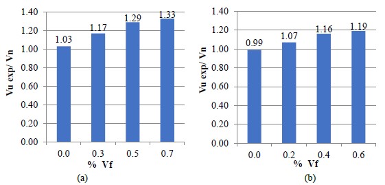
For the beams with a ratio w/c=0.55, the fiber increases up to 33% of the shear strength in comparison with the nominal strength for Vf=0.7%. In the case of the beams with a ratio w/c=0.35, the contribution of the fibers is less significant with a 19% for Vf=0.6%. This behavior shown in both beams may be due to the fibers that allowed for a reduction of the crack width caused by the diagonal tension, which brought about a redistribution of stresses in the stirrups, making them more efficient.
The effectiveness of the reinforcement with fibers together with the use of the stirrups was reported, where it was found out an improvement in the ultimate shear strength and in the ductility (Sarhat et al., 2006). The use of Vf of 0.5 and 1.5% resulted in a larger effectiveness than that resulted by increasing the w/c ratio. In table 8, it is even observed that the beams with ratio w/c=0.55, for all volume fibers, reached a higher experimental shear strength than those control beams with ratio w/c=0.35, even though the latter has a larger w/c ratio. This implies that at a higher volume of fibers (>0.5) the ratio w/c does not seem to have a significant effect.
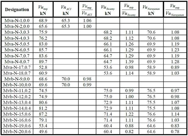
It can be noted, in table 9, the experimental results for the ultimate shear strength compared to the theoretical results obtained from the three analytical models studied. The effect of the w/c ratio of the beams can be observed for the experimental as well as for the theoretical results since the shear strength increases at lower w/c values. The best performance produced by the combination of stirrups and fibers, in comparison to the fiber-reinforced beams without stirrups, is also highlighted by the analytical models.
In table 9, it is presented a ratio of the experimental value to the theoretical value, to identify how much the ultimate shear strength is overestimated. The analytical models of Swamy and Narayanan predict values in most of the cases larger than the unit, i.e., they underestimate conservatively the experimental results. The three models show similar values to those from the experiments for both w/c ratios and for the fiber-reinforced beams with stirrups, however, for the beams without stirrups (17, 18, 19, and 20) the shear strength is overestimated for the ratio w/c = 0.35. Likewise, the effect of the volume fibers is also modeled adequately since it shows an increment of the ultimate experimental shear strength as Vf of the fiber also increases.
The conceptual criteria for which the three models were established explain the difference in their predictions of the experimental values, while the ACI model considers the contribution to the ultimate shear strength from the concrete, the fibers, and the stirrups, in the case of having them, and even the force due to the dowel effect. The Swamy model, which is considerably simpler, provides conservative values with respect to the experiments, and only the Narayanan model considers the tensile strength of the concrete. The two latter models consider the effect of the aspect ratio of the fiber and the variation of the Vf. It is worth mentioning that the analytical models studied do not provide information about the ductility and cracking patterns of the fiber-reinforced concrete beams.
| Table 9. Ratio between the experimental shear strength and the analytical shear strength obtained for each model | ||||||||||||||
 |
||||||||||||||
In similar manner, in table 9, it can be observed that, by analyzing the results of the beams without stirrups, Narayanan models overestimate the values and Swamy model does it similarly, but it is closer to the unit.
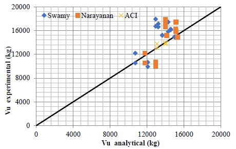
The graphical behavior of the aforementioned is presented in figure 3, where it can be observed a relationship between the results of the ultimate experimental shear strength and the results of the analytical models. It is noted that the prediction of the values obtained from the models that approach the diagonal is equal to the experiments, otherwise, all the values that are under this diagonal are slightly conservative. Such is the case for some points of the Narayanan model, which presents a lower degree of approximation with respect to the other analytical models proposes by Swamy and ACI. The majority of the plotted points of the three models show similitude in their results and they are considered conservative since they are over the diagonal.
5.3 Effect of the combined action of the reinforcement with steel fibers and stirrups.
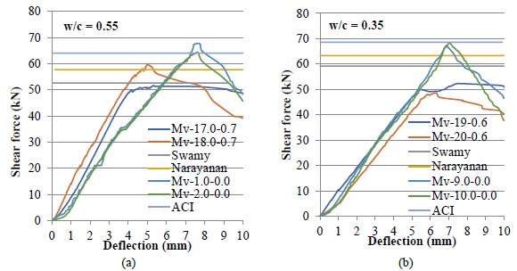
Figure 4 shows the results for the experimental shear strength of the fiber-reinforced concrete beams without stirrups, but with the higher fiber content, these are compared to the control beams and the limit values of the three studied models.
 |
||||
| Figure 4. Behavior of the fiber-reinforced beams without stirrups compared to the control beams. (a) Ratio w/c=0.55. (b) Ratio w/c=0.35. | ||||
In figure 4, it can be observed that for both w/c ratios the contribution of the maximum content of fiber into the experimental shear strength of the beams without stirrups (17, 18, 19, and 20) was not sufficient to at least reach the same experimental strength of the control beams (1, 2, 9, and 10) that have no fibers, but which have the higher amount of stirrups. Even just the beams with the ratio w/c = 0.55 reach the theoretical strength predicted by the models, this was not the case for the beams with ratio w/c = 0.35, this can be attributed to the lower Vf which leads to an insufficient increment of the concrete strength, nevertheless, it can be observed that the post-cracking behavior in the reinforced beams only with fibers had a lower reduction of the shear strength than those with only stirrups, this is due to the fiber-matrix adherence, which allows for the transfer of stresses. The control beams show an appropriate behavior and they reach the predicted value by the ACI.
On the other hand, it can be observed in figure 5, where the fiber-reinforced beams with the maximum Vf and with the lesser amount of stirrups had a higher shear strength than the control beams, even they were exceeded significantly for both w/c ratios the limit values of the models. The contribution of the fibers, in combination with half of the area of the transverse steel that the beams have, increased the ultimate shear strength with respect to the theoretical nominal strength, and this resulted to be larger in comparison to the results obtained for the control beams with the greater amount of stirrups.
 |
||||
| Figure 5. Behavior of fiber-reinforced beams with a minimum amount of stirrups compared with control beams. (a) Ratio w/c=0.55. (b) Ratio w/c=0.35. | ||||
From the reinforced concrete structural behavior point of view, the presence of the steel fibers as additional reinforcement for the beams with stirrups allows to increase in a significant manner the ultimate shear strength, hence, it is justifiable to use analytical models that admit predicting accurately a theoretical shear strength close to that experimentally obtained, and this can be a design aid for these types of structural elements.
The herein research showed that the ultimate shear strength increases substantially when steel fibers are used and that, by knowing analytical models of easy implementation, these can become a useful tool for the analysis and design of fiber-reinforced beams with stirrups and without them. Under this perspective, the conclusions that are applicable according to the results obtained are drawn next.
6. Conclusions
- The usage of steel fibers does not produce a decrease in the compressive and tensile strength of the fiber-reinforced concrete for both w/c ratios, on the contrary, both strengths increase.
- It is suggested to use experimental results for the compressive and tensile strengths obtained from the fiber-reinforced concrete specimens since this will allow the analytical models to have an appropriate prediction of the ultimate theoretical shear strength.
- The ACI, Swamy, and Narayana analytical models predicted conservative values with respect to the ultimate shear strength since they approach or are less than the experimental shear strength, this implies that they can be used conservatively for the analysis and design of fiber-reinforced concrete beams with stirrups.
- The use of Vf equal to 0.3, 0.5 and 0.7 in the fiber-reinforced beams with ratio w/c =0.55 with stirrups resulted in a higher experimental shear strength than the observed for the ratio w/c = 0.35.
- The fiber-reinforced concrete beams without stirrups with Vf equal to 0.6 and 0.7% have less ultimate shear strength than the control beams for both w/c ratios. In addition, the ultimate shear strength is lesser than the value predicted by the three analytical models.
- The steel fibers as additional reinforcement in combination with a minimum amount of stirrups allow increasing the ultimate shear strength substantially due to diagonal tension and the ductile behavior in the fiber-reinforced beams.
- The reinforcement executed only with steel fibers cannot substitute completely the transverse steel reinforcement, but it did show a better post-cracking behavior since it had a lower reduction of shear strength than the beams only with stirrups, this is caused by the fiber-matrix adherence.
7. Acknowledgements
The authors would like to thank Consejo Nacional de Ciencia y Tecnología (CONACYT), for the financial support for the master in science student scholarship. Also, they would like to thank the authorities of the Ingeniería Civil “Dr. Raymundo Rivera Villarreal” of the Facultad de Ingeniería Civil at UANL, for their support on the use of the required infrastructure to conduct the experimental tests.
References
ACI 318S-14, (2014), Requisitos de Reglamento para Concreto Estructural y Comentarios, Instituto Americano del Concreto, ACI.
Ashour, S. A., Hasanain, G. S., Wafa, F. F. (1992), Shear Behavior of High-Strength Fiber Reinforced Concrete Beams, ACI Structural Journal, Vol. 89, No. 2, March-April, pp. 176 - 184.
Aoude, H., Belghiti, M., Cook, W. D., Mitchell, D. (2012), Response of steel fiber-reinforced concrete beams with and without stirrups, ACI Structural Journal, Vol. 109, No. 3, pp. 359-367.
ASTM International. (2018). ASTM C33 / C33M-18, Standard Specification for Concrete Aggregates. Annual Book of ASTM Standards, American Society of Testing Materials. https://doi.org/10.1520/C0033_C0033M-18
ASTM International. (2020). ASTM A615 / A615M-20, Standard Specification for Deformed and Plain Carbon-Steel Bars for Concrete Reinforcement. West Conshohocken, PA. https://doi.org/10.1520/A0615_A0615M-20
ASTM International. (2016). ASTM A820 / A820M-16, Standard Specification for Steel Fibers for Fiber-Reinforced Concrete. West Conshohocken, PA. https://doi.org/10.1520/A0820_A0820M-16
ASTM International. (2020). ASTM C143 / C143M-20, Standard Test Method for Slump of Hydraulic-Cement Concrete. West Conshohocken, PA. https://doi.org/10.1520/C0143_C0143M-20
ASTM International. (2019). ASTM C192 / C192M-19, Standard Practice for Making and Curing Concrete Test Specimens in the Laboratory, Annual Book of ASTM Standards, American Society of Testing Materials. https://doi.org/10.1520/C0192_C0192M-19
ASTM International. (2021). ASTM C39 / C39M-21, Standard Test Method for Compressive Strength of Cylindrical Concrete Specimens. West Conshohocken, PA. https://doi.org/10.1520/C0039_C0039M-21
ASTM International. (2017). ASTM C496 / C496M-17, Standard Test Method for Splitting Tensile Strength of Cylindrical Concrete Specimens. West Conshohocken, PA. https://doi.org/10.1520/C0496_C0496M-17
ASTM International. (2017a). ASTM C231 / C231M-17a, Standard Test Method for Air Content of Freshly Mixed Concrete by the Pressure Method. West Conshohocken, PA. https://doi.org/10.1520/C0231_C0231M-17A
Dinh, H. H., Parra-Montesinos, G. J., Wight, J. K. (2010), Shear behavior of steel fiber-reinforced concrete beams without stirrup reinforcement, ACI Structural Journal, Vol. 107, No. 5, pp. 597-606.
Dupont, D., Vandewalle, L. (2003), Shear Capacity of Concrete Beams Containing Longitudinal Reinforcement and Steel Fibers, ACI Structural Journal, Vol. 216, pp. 79 - 94.
Haisam, E. Y. (2011), Shear Stress Prediction: Steel Fiber - Reinforced Concrete Beams without Stirrups, ACI Structural Journal, Vol. 108, No. 3, May-June, pp. 304 - 314.
Juarez, C., Valdez, P., Durán, A., Sobolev, K. (2007), The diagonal tension behavior of fiber reinforced concrete beams, Cement & Concrete Composites, 29(5):402-408. https://doi.org/10.1016/j.cemconcomp.2006.12.009
Jun Z., Jingchao L., Liusheng C. and Fuqiang S. (2018), Experimental Study on Shear Behavior of Steel Fiber Reinforced Concrete Beams with High-Strength Reinforcement. Materials, 11 (9), 1682, pp. 1-19. https://doi.org/10.3390/ma11091682
Khuntia, M., Stojadinovic, B. (2001), Shear Strength of Reinforced Concrete Beams without Transverse Reinforcement, ACI Structural Journal, Vol. 98, No. 5, September-October, pp. 648 - 656.
Marì Bernat, A., Spinella, N., Recupero, A. (2020), Mechanical model for the shear strength of steel fiber reinforced concrete (SFRC) beams without stirrups. Materials and Structures. 53(28). https://doi.org/10.1617/s11527-020-01461-4
Narayanan, R., Darwish, I. Y. S. (1987), Use of Steel Fibers as Shear Reinforcement, ACI Structural Journal, 84 (3), May - June, pp. 216 - 226.
Organismo Nacional de Normalización y Certificación de la construcción y Edificación, S.C. (ONNCCE) (2017). NMX-C-414-ONNCCE: Industria de la Construcción - Cementos Hidráulicos - Especificaciones y Métodos de Prueba. Norma Mexicana.
Park, P., Paulay, T. (1990), “Estructuras de Concreto Reforzado”, Editoriales Limusa y Noriega, Nueva Edición, pp. 288 - 294. https://www.u-cursos.cl/usuario/7ed3df485e955c4de1ffa12120d4bb52/mi_blog/r/estructuras_de_concreto_reforzado_-_r._park___t._paulay.pdf
Sarhat, S. R., Abdul-Ahad, R. B. (2006), The Combined Use of Steel Fibers and Stirrups as Shear Reinforcement in Reinforced Concrete Beams, SP, American Concrete Institute, vol. 235, pp. 269 - 282.
Shin, S. W., Oh, J. G., Ghosh, S. K. (1994), Shear Behavior of Laboratory-Sized High Strength Concrete Beams Reinforced with Bars and Steel Fibers, American Concrete Institute, Volume 142. pp. 181-200.
Swamy, R. N., Bahía, H. M. (1985), The Effectiveness of Steel Fibers as Shear Reinforcement, Concrete International, Design and Construction, Vol. 7, No. 3, March, pp. 35 - 40.
Swamy, R. N., Mangat, P. S., Rao, C. V. S. K. (1974), The Mechanics of Fiber Reinforcement of Cement Matrices, Symposium Paper, American Concrete Institute, 44, pp. 1 - 28.
Swamy, R. N., Narayan, J., Roy Chiam, T. P. (1993), Influence of Steel Fibers on the Shear Resistance of Lightweight Concrete I - Beams, ACI Structural Journal, Vol.90, No. 1, January - February, pp. 103 - 114. https://doi.org/10.14359/4201