| Study Case | https://doi.org/10.21041/ra.v11i1.485 |
Advances in the implementation of optical fiber on structures. The present of an implementation with a future
Avanços na instrumentação de estruturas com fibra ótica. o presente de uma instrumentação com futuro
Avances en la instrumentación de estructuras con fibra óptica. El presente de una instrumentación con futuro
1 , Profesor Asociado Departamento de Ingeniería Civil y Ambiental, UPC, Barcelona, España..
2 , Profesor Asociado Departamento de Ingeniería de Proyectos y de la Construcción, UPC, Barcelona, España.
*Contact author: info@cotca.com
Reception: November 14, 2019.
Acceptance: October 30, 2020.
Publication: January 01, 2021.
| Cite as: Alegre, V., Villalba, S. (2021), "Advances in the implementation of optical fiber on structures. The present of an implementation with a future", Revista ALCONPAT, 11 (1), pp. 105 – 122, DOI: https://doi.org/10.21041/ra.v11i1.447 |
Abstract
An example of a real case is discussed in which, on an existing tunnel, which is instrumented with optical fiber, a building is built. This makes possible to track the load history of a structure since the fiber is placed. To verify that the tunnel is not structurally affected during the construction period, sections of it are instrumented and the micro deformations that occur are measured, which are compared with those of the model. It has been possible to appreciate the ovalizations and tensions in the vault during the different phases of the construction process, all of them being below the limit values established in the contingency plan. This technique has made possible to validate the works carried out throughout the process.
Keywords:
optical fiber,
instrumentation,
tunnels,
microdeformations
Resumo
É discutido o exemplo de um caso real em que, em um túnel existente, um edifício é construído com instrumentação de fibra ótica que permite monitorar o histórico de carregamento de uma estrutura desde sua instalação. Para verificar se o túnel não é estruturalmente afetado durante o período de construção, trechos do túnel são instrumentados e as microdeformações ocorridas são medidas, as quais são comparadas com as do modelo. Foi possível apreciar as ovalizações e tensões na abóbada durante as diferentes fases do processo de construção, estando todas abaixo dos valores limites estabelecidos no plano de contingência. Esta técnica permitiu validar os trabalhos realizados ao longo do processo.
Palavras-chave:
fibra ótica,
instrumentação,
túneis,
microdeformações
Resumen
Se discute el ejemplo de un caso real en el que, sobre un túnel existente que se instrumenta con fibra óptica, se construye un edificio. Ello permite hacer el seguimiento de la historia de cargas de una estructura desde que se coloca la fibra óptica. Para constatar que no se ve afectado estructuralmente el túnel durante el período de construcción, se instrumentan secciones del mismo y se miden las microdeformaciones que se producen, que se comparan con las del modelo. Se han podido apreciar las ovalizaciones y tensiones en la bóveda durante las distintas fases del proceso constructivo, estando todas ellas por debajo de los valores límites establecidos en el plan de contingencias. Esta técnica ha permitido validar durante todo el proceso las obras realizadas.
Palabras clave:
fibra óptica,
instrumentación,
túneles,
microdeformaciones
1. Introduction
A common technical problem is the interaction between newly built works and existing infrastructures. The different parts of an infrastructure are managed for a lifespan, as is the case of the Barcelona Metro Network, whose current state was defined in an orderly manner between 2000 and 2003 leaving, among other documents, a 92 km - virtual tunnel, then with the geometry of the cross section and the catalogue of damage and dysfunctions for its management. The first kilometers of tunnel are from 1924 and, logically, the responsible administration (Generalitat de Catalunya) and the body that manages it (Transports de Barcelona, S.A.) require that in the new built buildings, within the area of influence of its infrastructure, it is verified that they do not affect the use and service of the network nor its structure. To this end, inter alia, it requires that the affected area be structurally assessed by providing the structural information available to it, and that the movements that occur in the infrastructure during the construction of the new work be recorded, acting accordingly.
To track this, measurements are sometimes made with monitored theodolites from various points in the cross section. If more precision is desired to assess risks, a very valid tool is optical fiber technology that, attached to the surface, allows to measure microdeformations in, for example, the cross sections centimeter by centimeter.
This technology consists of the use of an optical backscatter reflectometer called the OBR (Optical Backscatter Reflectometer) system as a monitoring tool, in this case, of a reinforced concrete structure of a tunnel with dovelas of Line 9 in Barcelona, which could present cracks or dysfunctions in service, as a result of the construction of a building that is partially carried out on that section of tunnel.
The main feature of the OBR system is its high sensitivity and high spatial resolution using optical fiber as a sensor. This produces deformation records in which the presence of cracks can be identified and located.
On this tunnel a building will be made, having modeled the whole process: emptying, foundation slab, execution of the structure and loading of all the subsystems that are part of the building (facades, pavements, partition, installations, ...).
For these loading stages, the expected values are set, and a contingency plan is created with warnings, alerts, and alarms in case they are exceeded. As the work progresses, the instrumentation carried out in the tunnel with the optical fiber registers the values obtained continuously or semi-continuously, which allows to know at all times the possible dysfunctions that occur in the section (ovalizations, microdeformations, new fissures, etc.) and act accordingly. The period provided for the execution of the work is 18 months, once the work is finished, the implementation could be maintained and readings could be made when, for example, incidents occurred and its impact on the structure of the tunnel from which its "history of loads" is obtained.
Optical fiber, which as a continuous monitoring system is resistant to water and corrosion, avoids problems of electromagnetic interference and currents that occur in other techniques, and allows simultaneous readings of up to 5000 points of the structure under study.
The objective of this work is to find that the tunnel is not structurally affected during the construction period of the building, through the implementation of sections of the former in which the microdeformations that occur are measured, and which are compared to those of the model. In this way, ovalizations and tensions can be observed in the vault during the different phases of the construction process.
2. Modelling and instrumentation of the tunnel
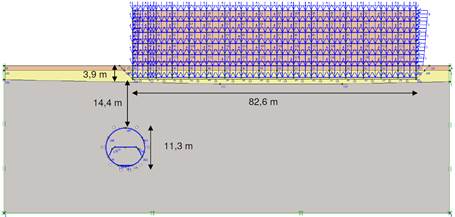
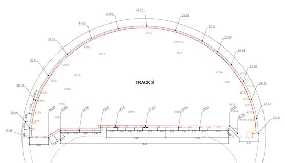
The modelling of the different stages was carried out with the SAP2000 program and the two-dimensional PLAXIS, and gave, from the geometry defined in Figure, the following results indicated in Figure 1, Table 1 and Figure 2:
 |
||||
| Figure 1. Geometry of the calculation section | ||||
| Table 1. Results obtained in the model | ||||||||||||||
| In the current situation | Parking excavation phase | Building operation phase | ||||||||||||
|---|---|---|---|---|---|---|---|---|---|---|---|---|---|---|
| Tunnel cladding efforts | ||||||||||||||
| Nk (kN/m) | 1.430 | 1.410 | 1.700 | |||||||||||
| Vk (kN/m) | 39,63 | 38,44 | 45,04 | |||||||||||
| Mk (kN-m/m) | 33,45 | 34,10 | 61,66 | |||||||||||
| Maximum displacements in the tunnel | ||||||||||||||
| Horizontal (mm) | 0 (*) | 1,49 | -2,98 | |||||||||||
| Vertical (mm) | 0 (*) | 1,63 | -7,18 | |||||||||||
| (*) The current situation is adopted as a reference situation, that is, deformation state 0. | ||||||||||||||
 |
||||
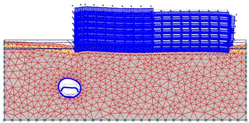
| Figure 2. First breakage mechanism found, for a safety factor of 2.29. | ||||
As a result of the above, a contingency plan was established which is summarized in Table 2.
| Table 2.Maximum tensions and deformations in voussoirs. Contingency plan. | ||||||||||||||
| Compression zone values | Traction zone values | |||||||||||||
|---|---|---|---|---|---|---|---|---|---|---|---|---|---|---|
| Voussoirs | Voussoirs | |||||||||||||
| (MPa) | Δμε | Crack width (mm) | ||||||||||||
| Notice | 18.40 | 755 | 0.50 | |||||||||||
| Alert | 28.40 | 955 | 1.80 | |||||||||||
| Alarm | 33.40 | 1595 | 3.50 | |||||||||||
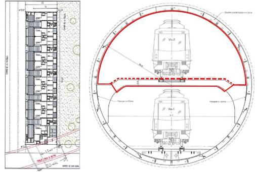
The L9 instrumented tunnel is a typical section with overlapping tracks and intermediate steed. The optical fiber has been placed on the perimeter of the cross section, always according to the Property.
 |
||||
| Figure 3. shows its placement. Fiber placement has been carried out following the perimeter of a cross section in the position indicated in the plant. | ||||
The proposed instrumentation measures microdeformations in the cross-section of the tunnel, i.e. possible movements, or dysfunctions of the cross section.
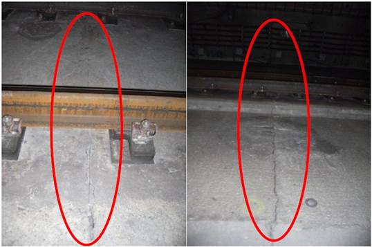
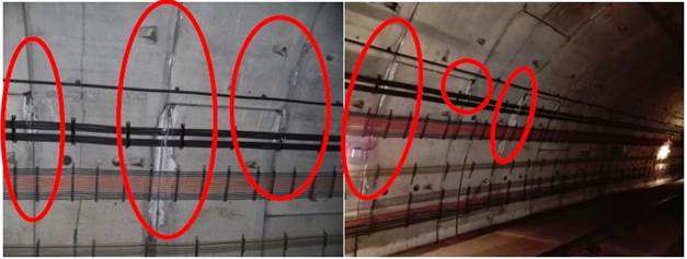
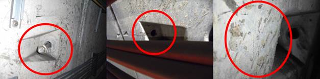
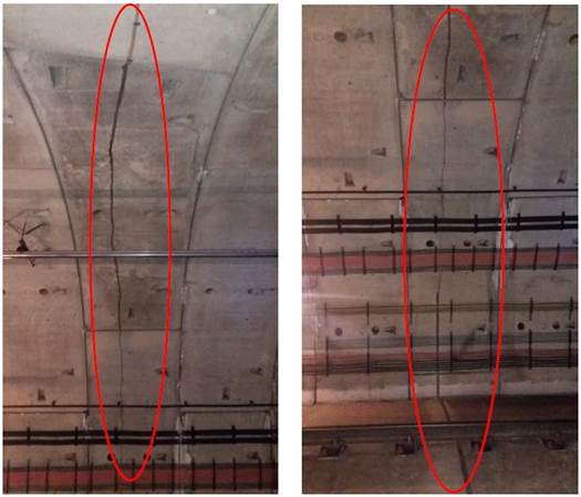
In the initial reading of zeros with optical fiber a catalogue of current dysfunctions (cracks, humidity, coqueries, anomalous roughness, etc.) is made. Figure 4, Figure 5 and Figure 6 show some of the found dysfunctions in the initial inspection.
 |
||||
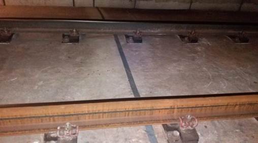
| Figure 4. Joints on the track, which exist every 25m. | ||||
 |
||||
| Figure 5. Filtrations (leachings of cement limes). | ||||
 |
||||
| Figure 6. Roughness and clamping bolts that could affect the placement of the fiber. | ||||
At each subsequent reading raised in the different phases of the work (pre-start, emptying, completion of the foundation, structure and purpose of the work), microdeformations are measured in the perimeters of the cross sections, compared to the model made and reports are issued. Where the ovalization criteria prescribed in the regulations are exceeded or dysfunctions are detected, action shall be taken in accordance with the established contingency plan protocol.
This allows to detect the main changes in the structural behavior of the tunnel and obtain information that will serve to evaluate its structural safety, during the construction of the building, at the end of the works and throughout its useful life.
2.1 Positioning schemes
The entire monitoring system has been located in the strategic area susceptible to the possible dynamics and evolution of the structural response (variations of microdeformations-stresses, movements, possible increments and / or development of cracking maps, etc.) of the tunnel throughout the construction work of the building. This instrumentation system has been selected considering the working conditions to which it will be subjected (thermal variation, conditions of use, etc.).
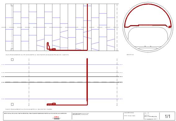
Below is the scope of monitoring used (see Figure 7).
 |
||||
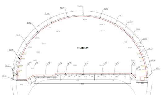
| Figure 7. General tunnel scheme. Elevation and plant. The red line indicates the path of the optical fiber. | ||||
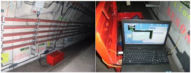
The actual tunnel monitoring length is adjusted to the actual length of a cross section and longitudinal section, this being 50.00m in length. That is, FOD1 optical fiber (Distributed Optical Fiber) is attached 40m and the last 10m were kept on the reel containing the optical fiber (without attaching), which was attached to the structure with American tape. This detail is shown in Figure 8, Figure 9 and Figure 10 along with the system installed within the tunnel cross section.
 |
||||
| Figure 8. Remaining optical fiber reel subject to the structure and ODiSI (Optical Distributed Sensor Interrogator, by LUNA Tecnologies, Model A50) in operation. | ||||
 |
||||
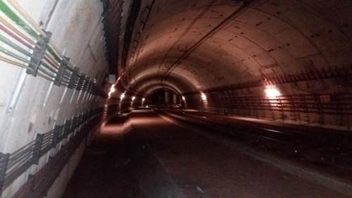
| Figure 9. Overview of the tunnel in the instrumented section. | ||||
 |
||||
| Figure 10. Optical fiber protected under train tracks. | ||||
Figure 11 shows the adhesion procedure performed with the optical fiber on the traffic lane steed of track 2 and in the tunnel vault.
 |
||||
| Figure 11. Optical fiber adhesion procedure on the steed of the track 2 circulation lane and in the tunnel vault. | ||||
3. Results and discussion.
3.1 Model results
Tensions and displacements have been obtained in the tunnel before, during and after the construction of the building by means of a method of calculation by finite elements in scenarios of flat deformation. The software used is PLAXIS v8.
The following are the most significant results obtained from the monitoring raised, as seen in Figure 12 FOD processing.
 |
||||
| Figure 12. Tunnel section and FOD processing. | ||||
Table 3 of Figure 13, Figure 14, Figure 15, Figure 16 and Figure 17 with the work process carried out:
| Table 3. Identification of figures. | ||||||||||||||
| Figure | Stage | Day / Range of days | FOD length | |||||||||||
|---|---|---|---|---|---|---|---|---|---|---|---|---|---|---|
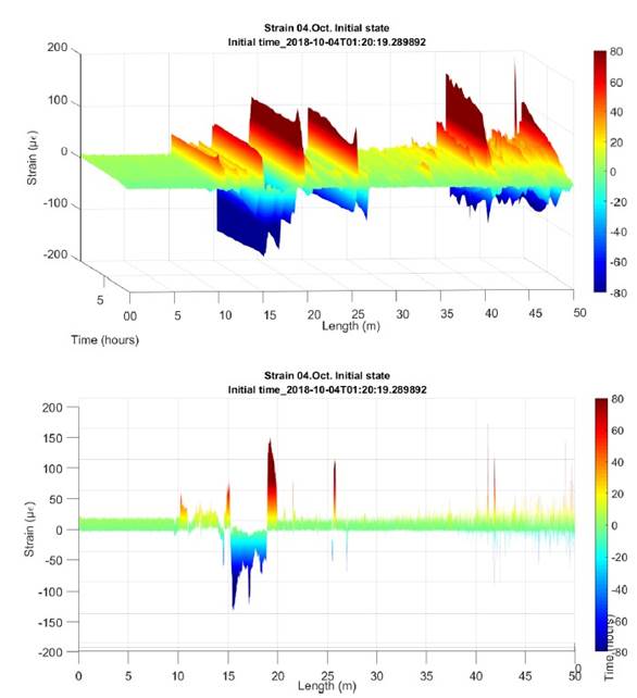
| Figure 13 | Initial status | 4 oct. | Total length: 50 m | |||||||||||
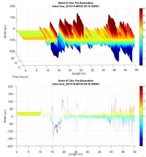
| Figure 14 | Pre-excavation | 7 Oct. | Total length: 50 m | |||||||||||
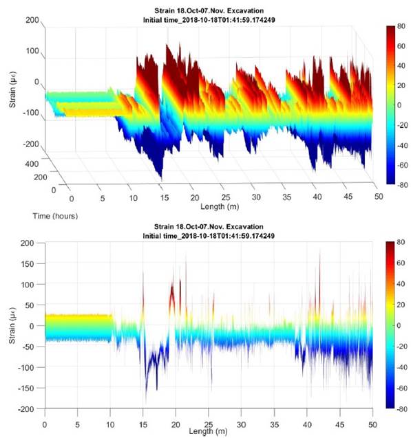
| Figure 15 | Excavation | 18 Oct. – 07 Nov. | Total length: 50 m | |||||||||||
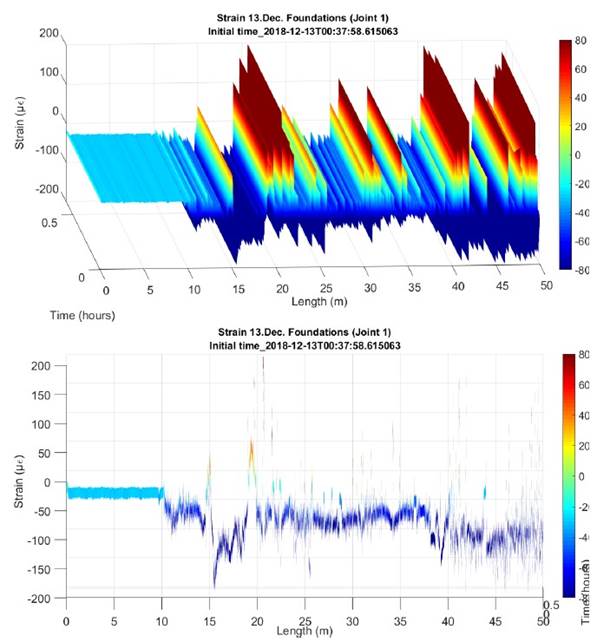
| Figure 16 | Concrete foundation | 13AD.c. | Total length: 50 m | |||||||||||
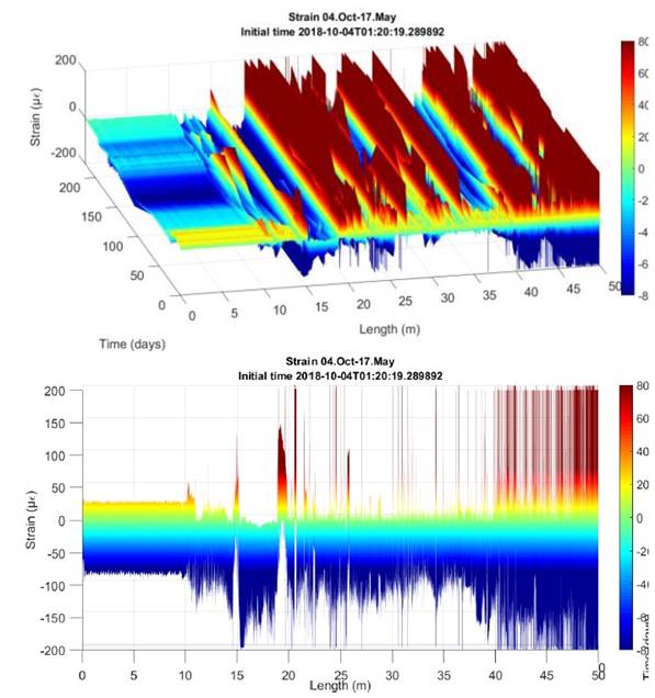
| Figure 17 | Temporary evolution | 4 oct. – 17 May. | Total length: 50 m | |||||||||||
INITIAL STATE
 |
||||
| Figure 13. Initial and calibration status. Length 50m FOD. Axonometric and frontal view. | ||||
PRE-EXCAVATION
 |
||||
| Figure 14. Pre-excavation. Length 50m FOD. Axonometric and frontal view. | ||||
EXCAVATION
 |
||||
| Figure 15. Complete excavation. Length 50m FOD. Axonometric and frontal view. | ||||
EXECUTION 1ST FOUNDATION SECTION
 |
||||
| Figure 16. Execution of first section on foundation slab. Length 50m FOD. Axonometric and frontal view. | ||||
TOTAL EVOLUTION
 |
||||
| Figure 17. Temporary evolution of 4 October and 17 May. Length 50m FOD. Axonometric and frontal view. | ||||
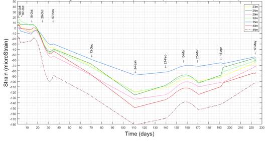
Figure 18 and Figure 19 incorporate the reading log at 6 critical points along the tunnel vault section.
 |
||||
| Figure 18. Identification of critical control points in the Tunnel vault. | ||||
 |
||||
| Figure 19. Temporary evolution from October 4, 2018 to May 17, 2019 at critical checkpoints. | ||||
It is generally noted that:
- The fiber section between 40 and 50m??? corresponds to the track area. In this section is where there is more excitement of the fiber given the railway step. The vibration caused by the railway circulation results in more distortion of readings in this section. Even so, it is observed how these variations of recorded microdeformations have a tendency to increase to compression, which is consistent with the decompression and ovalization suffered by the curved section of the tunnel and which causes the slab to perform a strut function in response of this action. The ovalization of the tunnel is explained at the next point. Likewise, under no circumstances do the obtained values exceed the notice limit set out in the Auscultation and Contingency Plan.
- The fiber section between 23 and 40m ???corresponds to the area of the vault. This section shows how, in general, there has been an increase in compression microdeformations throughout the instrumentation. This is due to the decompression caused by the excavation and emptying of land from the work, so that this decompression produces a certain "ovalization" of the section, which results in an increase in compression in the inner fiber of the section (the inner fiber of the section is compressed and the outer fiber of the decompression section). It can be clearly seen as going from a green color (null and initial deformation) to a blue color indicating compression. Likewise, under no circumstances do the obtained values exceed the notice limit set out in the Auscultation and Contingency Plan.
- With regard to stress analysis and from the definition of the concrete Ec drying longitudinal deformation module and for a state of stresses under service conditions, i.e. for an elastic state or stage where the stresses of the concrete fibers of the section are proportional to the deformations, it is apparent that, even if observing this increase of ????, they do not induce excessive stresses on it.
- The fiber bouquet between 10 and 23m corresponds ??? to the longitudinal monitoring section. In this area we see values for compression and traction, but that throughout their evolution have been constant at all times, that is, without variation in the origin of the readings and calibration. This fact indicates that there have been no variations in this section in response to the structure, i.e. that the actions carried out have not led to appreciable changes in the structure.
- The fiber section between 0 and 10m??? corresponds to the non-adhered fiber section. In this area there is a linear evolution without differential changes, where it is found that there are no substantial variations in temperature that induce significant tension variations, so that they do not influence the other zonas areas of FOD attached.
In addition, peaks and/or discontinuities obtained from monitoring can be seen, which correspond to the joint areas between sections of the dovelas where the optical fiber suffers a disadherence with the concrete, since its implementation at source. These peaks remain stable in terms of their location.
4. Conclusions
The use of Optical Backscatter Reflectometer sensors is a promising technology for structural status monitoring, as it allows the possibility of continuous monitoring over time and voltage and temperature space along the fiber.
A tunnel section is being monitored, which has, to date, carried out a control of the structure in service during the eight months (October 2018 - May 2019) covering the construction of the structure of a building on the track, up to the 1st floor level, in the building area above the tunnel.
Monitoring has been used to identify and technically characterize the increases in traction and compression stresses, as a result of the different phases of the work, from before we begin, with the previous calibration readings to the construction phase of the structure, in which we find ourselves. Monitoring will continue until the end of the work, scheduled for November 2020.
During this 8-month period, the microdeformation variations of FOD 1 fiber have been 153 which translated to stresses represent a maximum voltage variation of 5.75MPa.
These values are acceptable for such structures, as they are compression values in concrete. On the other hand, these values include thermal effects.
From the variations obtained in the monitoring of FOD 1 fiber throughout this medium thermal cycle, the impact of thermal action on the tunnel can be considered to have been negligible
Once it has been confirmed that the tunnel is in adequate safety conditions and once the work is finished, a permanent register will be available to access the section, and to be able to perform intermittent readings throughout its lifespan to know the deferred behavior. This has been raised within the mandatory tunnel maintenance plan.
5. Acknowledgements
The technicians of IMHAB (Institut Municipal del Habitatge i Rehabilitació de Barcelona) and TMB (Transports de Barcelona, S.A.) are thanked for the facilities given for the management of all operations.
References
Li, H., Li, D., Song, G. (2004), “Recent applications of fiber optic sensors to health monitoring in civil engineering”. Engineering Structures, Volume 26, Issue 11, pp. 1647-1657. https://doi.org/10.1016/j.engstruct.2004.05.018
Villalba, S., Casas, J. R. (2009), “Feasibility of Structural Health Monitoring of concrete structures by Optical Backscatter Reflectometer”. Proceedings of 7th International Workshop on Structural Health Monitoring. Stanford University (USA).
Alegre, V., Villalba, S. (2013), “Estructuras inteligentes. Instrumentación con fibra óptica”. XII Congreso Latinoamericano de Patología de la Construcción y XIV Congreso de Control de Calidad en la Construcción. CONPAT-2013. Colombia 2013. ISBN 978-958-58090-0-0.
Alegre, V., Villalba, S., Force, F., Ródenas, V. (2015), “Apeo y sustitución de un pilar de fábrica de ladrillo en un edificio modernista en uso”. XIII Congreso Latinoamericano de Patología de la Construcción y XV Congreso de Control de Calidad en la Construcción. CONPAT-2015. Lisboa 2015.
Control de Calidad Alegre, V., Villalba, S. (2017), “Avances en la instrumentación con fibra óptica”. XIV Congreso Latinoamericano de Patología de la Construcción y XVI Congreso de Control de Calidad en la Construcción. CONPAT-2017. Vol. I. . ISBN 978-99967-0-464-2.