
| Basic Research | https://doi.org/10.21041/ra.v10i2.482 |
Image analysis on disintegrated concrete at the post-heating stage
Análise de imagem em concreto desintegrado na fase de pós-aquecimento Análisis de imagen sobre concreto desintegrado en la etapa de postcalentamiento
1 Department of Civil Engineering, Yıldız Technical University, İstanbul, Turkey.
2 Department of Civil Engineering, İstanbul, Turkey.
*Contact author: aakca@yildiz.edu.tr
Reception: November 02, 2019.
Acceptance: February 05, 2020.
Publication: April 30, 2020
| Cite as: Akcal, A. H., Özyurt, N. (2020), "Image analysis on disintegrated concrete at the post-heating stage", Revista ALCONPAT, 10 (2), pp. 219 – 229, DOI: http://dx.doi.org/10.21041/ra.v10i2.482 |
Abstract
The relation between crack growth and reduction in the compressive strength after high temperature exposure and after air re-curing was investigated in this study. Concrete specimens were heated to 1000 ºC and they were subjected to air re-curing for 28 days. During re-curing period, their heated surfaces were monitored by using a digital single-lens reflex camera and the images were analyzed by using image analysis software. After cooling, the maximum reduction in the compressive strength of concrete was 49.5% and that of air re-cured concrete was 66.8%. Image analyses showed high correlations between crack growth and reduction in the compressive strength. This non-destructive method has the potential to represent the extent of damage in concrete after high temperature exposure.
Keywords:
high temperature,
fiber reinforced concrete,
deterioration,
crack development,
black,
temperatura alta,
concreto reforçado com fibra,
deterioração,
desenvolvimento de fissuras,
análise de pixel preto.,
alta temperatura,
concreto reforzado con fibra,
deterioro,
desarrollo de grietas,
análisis de píxeles negros.
Resumo
A relação entre o crescimento de fissuras e a redução da resistência à compressão após exposição a altas temperaturas seguidas de resfriamento lento e ao ar foi investigada neste estudo. As amostras de concreto foram aquecidas a 1000 ºC e, após submetidas ao resfriamento lento foram, na sequência sazonadas ao ar por 28 dias. Durante o período de resfriamento, sua superfície foi monitorada usando uma câmera reflex digital de lente única e as imagens foram analisadas usando o software de análise de imagens. Logo após o resfriamento, a redução máxima na resistência à compressão do concreto foi de 49,5% e a do concreto sazonado ao ar, após 28 dias, foi de 66,8%. As análises de imagem mostraram altas correlações entre o crescimento da fissura e a redução da resistência à compressão. Este método não destrutivo tem o potencial de representar a extensão dos danos no concreto após a exposição a altas temperaturas.
1. Introduction
Thermal gradients, evaporation of free water and chemical changes in concrete are the main reasons of deteriorations such as crazing, surface delamination, cracking and spalling (Poon et al. 2001; Akca and Özyurt, 2013) Moreover, deterioration in concrete may continue in the subsequent days of cooling due to continuing changes occurred in microstructure of concrete. For example, rehydration of CaO results in Ca(OH)2 with a 44% volume expansion and this reaction may cause cracking of concrete especially at the heated surface level (Lin et al. 1996; Alonso and Fernandez, 2004; Mendes et al. 2011).
The changes on the heated surfaces of concrete can be used to evaluate the residual properties of concrete after heat exposure. For example, color changes on heated or fire exposed concrete surfaces give information about maximum temperature experienced and amount of deterioration of concrete (Yüzer et al. 2004; Ingham, 2009). Pink to red coloration occurs due to oxidation of iron compounds in sand particles after 300 ºC and whitish color concrete surface means that temperature of concrete exceeded 700 ºC at which decarbonation of carbonates takes place. Thus, reduction in strength can be predicted roughly without applying destructive tests on concrete in some cases.
Similarly, cracks on the heated surfaces can be evaluated to predict residual concrete strength after cooling. Therefore, concrete specimens were subjected to air re-curing process after heating up to 1000°C. In this project, one face heating condition was applied to the specimens since it can be considered more realistic and applicable. Then, heated surfaces of concrete specimens were monitored by using a DSLR camera after cooling and the images were evaluated to understand the relation between crack width and crack growth rate on the heated surfaces and the reduction in compressive strength after heating.
2. Experimental study
2.1 Materials and specimens
CEM I type Portland cement (PC) was used in concrete groups and total amount of cement in 1 m3 of concrete was 450 kg and all concrete groups had a water to cement ratio of 0.45. Table 1 shows mix proportions of concrete groups. As chemical admixtures, oil alcohol and ammonium salt-based air entraining admixture (AEA) and modified polycarboxylate based superplasticizer were used in concrete mixes. AEA content was the same and 0.3 kg (0.7 % of total weight of cement.) in all concrete groups. Super plasticizer amount was varied in order to obtain slump levels in S4 limits given in EN 206-1. Steel fibers were used as high melting point fibers and PP fibers were used as low melting point fibers to reinforce concrete groups. In PP fiber reinforced groups PP fibers were used 0.2 % of volume of concrete and in steel fiber reinforced groups steel fibers were used 0.5 % of volume of concrete. PP fibers and steel fibers were added at contents of 0.1 % and 0.25 % per volume in hybrid fiber reinforced concrete groups, respectively. River sand and siliceous gravel were used in all concrete groups as aggregates. Depending on fiber types and also presence of air entraining agent, 8 different concrete groups were designed as can be seen in Table 1.
11 cubic specimens with dimensions of 15x15x15 cm were produced for each concrete group. One day after production, specimens were demolded and placed in curing water for 27 days. Then they were conditioned in laboratory environment for additional 2 months before tests (Poon et al. 2001; Chang et al. 2006). Three cubic specimens were used to determine initial properties of concrete before heating. Remaining 8 cubic specimens were heated to 1000 °C. Two of them were used to monitor temperatures in concrete cubes during heating, 3 of them were tested to determine properties after cooling and remaining 3 cubic specimens were subjected to air re-curing. Therefore, in tables and graphs 0, X, and Z represent tests before heating, after cooling and after air re-curing, respectively.
| Table 1. Mix proportions. | ||||||||||
| Series | W/C | Cement | Water | Crushed Stone | Crushed Sand | Sand | SPa | AEA | PP Fibers | Steel Fibers |
|---|---|---|---|---|---|---|---|---|---|---|
| (kg/m3) | (dm3/m3) | |||||||||
| C00 | 0.45 | 450 | 202.5 | 968 | 565 | 225 | 5.7 | - | - | - |
| C0S | 0.45 | 450 | 202.5 | 968 | 565 | 225 | 6.0 | - | - | 5 |
| C0P | 0.45 | 450 | 202.5 | 968 | 565 | 225 | 6.3 | - | 2 | - |
| C0H | 0.45 | 450 | 202.5 | 968 | 565 | 225 | 6.6 | - | 1 | 2.5 |
| CA0 | 0.45 | 450 | 202.5 | 968 | 565 | 225 | 5.3 | 0.3 | - | - |
| CAS | 0.45 | 450 | 202.5 | 968 | 565 | 225 | 5.7 | 0.3 | - | 5 |
| CAP | 0.45 | 450 | 202.5 | 968 | 565 | 225 | 6.0 | 0.3 | 2 | - |
| CAH | 0.45 | 450 | 202.5 | 968 | 565 | 225 | 6.6 | 0.3 | 1 | 2.5 |
| SP stands for superplasticizer | ||||||||||
2.2 Heating procedure
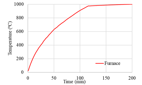
An electrical furnace which has a 1250 °C maximum operation temperature was used in this study. Two stages of heating were determined and during the first stage, specimens were heated to 1000 °C and during the second stage specimens were kept at this temperature until the end of the total heating time (200 minutes). Figure 1 represents the heating procedure. Electrical furnace was operated at full power and temperature inside the furnace reached 1000 °C in approximately 120 minutes. Since furnace heating capacity was limited, heating rate was 20°C/min at the beginning but the rate decreased to 5 °C/min at the end of the first stage of heating. After the second stage completed, hot concrete specimens were not taken out until the furnace cooled down to 100 °C.
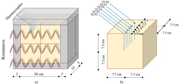
Four concrete cubes were placed together in the electrical furnace and in order to simulate one face heating conditions they were insulated with aerated concrete blocks as shown in Figure 2. For temperature monitoring K-Type thermocouples were placed inside a concrete specimen during heating.
2.3. Re-curing process
After heating and cooling processes 3 specimens were subjected to air re-curing for 28 days. Specimens were kept in laboratory environment which has a relative humidity of 65±10% and temperature of 20±2°C during re-curing period.
2.4. Crack width measurements
Visual changes on heated or fire exposed concrete give information about maximum temperature experienced and amount of deterioration of concrete (Yüzer et al. 2004; Ingham, 2009). Therefore, photograph of the heated face of a survived specimen from each concrete group was taken by using a DSLR camera. These pictures were analyzed via software called Image J as can be seen in Figure 3. During an analysis the whole picture area was divided into 9 subareas and maximum crack widths of each subarea were measured and then mean crack widths were obtained.
2.5. Black pixel analyses
Development of cracks during air re-curing was monitored by taking photos of heated surfaces at every hour for a week. A high resolution DSLR camera and a 100 mm macro lens were used in order to obtain detailed images. As can be seen in Figure 4, these images were converted to 8-bit black and white images by using Image J and black pixel analyses (BPA) were conducted on them.
Black pixels represent cracks, air voids, surface delamination and shadow (due to positions of spotlights) on the heated surfaces of specimens. Total areas of black pixels were calculated for all images separately. Then these calculated values were divided to black pixel area of first image in order to obtain normalized area values. Finally, normalized area-time graphs were drawn for all concrete groups except the groups experienced spalling during heating and trend lines were fitted on the graphs as shown in Figure 5. These curves were used to monitor deterioration of concrete for a week. The slopes of fitted trend lines were called BPA rates and they were compared to compressive strength reduction ratios of air re-cured concrete groups.
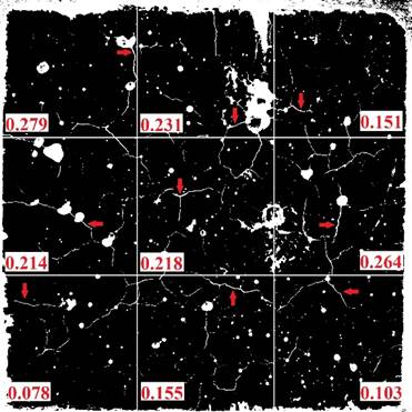
Figure 3.
Crack width measurements on a C00X specimen (surface just after cooling).
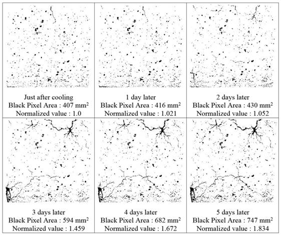
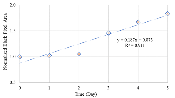
Figure 5.
Black pixel analysis value of C0PZ specimen.
3. RESULTS
3.1. Temperature monitoring
Temperatures of heated surface and inner parts of concrete cubes were monitored during heating and temperature monitoring continued further during cooling of the furnace (150 minutes more). In cooling period, although heating of furnace was stopped, temperatures in concrete continued to increase. Thermocouple data was very close when they were compared in terms of cementitious material types. Therefore, all concrete groups were gathered under two categories depending on use of AEA in them. Table 2 shows average maximum temperatures monitored in concrete categories with and without air entrainment during total temperature monitoring (200+150 minutes). Results showed that, temperatures experienced in air entrained concrete were less than that of concrete without air entrainment. When the whole heating and cooling period is considered it can be seen that concrete groups experienced at least 583 °C of temperature which may result in severe strength losses (Poon et al. 2001; Akca and Özyurt, 2013).
| Table 2. Average maximum temperature values at predefined depths from the surface during total heating and cooling processes (at the end of 350 minutes). | ||||||||||
| Thermocouple No | TC#1 | TC#2 | TC#3 | TC#4 | TC#5 | TC#6 | ||||
|---|---|---|---|---|---|---|---|---|---|---|
| Depth (mm) | 0 | 19 | 38 | 57 | 75 | 113 | ||||
| Without AEA¹ (°C) | 1000 | 805 | 691 | 657 | 636 | 608 | ||||
| With AEA² (°C) | 1000 | 784 | 662 | 627 | 608 | 583 | ||||
| Difference (°C) | 0 | 21 | 29 | 30 | 28 | 25 | ||||
| Without AEA¹ stands for all concrete groups without air entrainment. With AEA² stands for all concrete groups with air entrainment. | ||||||||||
3.2. Compression tests
Cubic concrete specimens were loaded before heating, after cooling and after air re-curing (for 28 days) and compressive strength values of concrete groups were determined at every stage. Compressive strength values of all concrete groups decreased after heating and further reduction in residual strength was observed after air re-curing period. Reduction ratios in compressive strength of all concrete groups after cooling and after air re-curing can be seen in Table 3.
Table 3. Reduction in compressive strength with respect to before heating strength.
Reduction in compressive strength
C00
C0S
C0P
C0H
CA0
CAS
CAP
CAH
After cooling (%)
31.9
25.8
36.7
33.9
35.2
36.5
49.5
45.5
After air re-curing (%)
64.1
44.9
66.8
49.2
56.3
49.6
58.7
56.5
3.3. Crack width measurement (after cooling specimens)
Photographs of the heated face of a survived specimen from each concrete group were taken by using a DSLR camera. These pictures were analyzed via software called Image J, then mean crack widths were obtained. Average crack widths of concrete groups after cooling were given in Table 4. According to the results it can be concluded that there were cracks on the heated faces of the specimens around 0.20 mm after heating. Also cracking tendency of PP fiber reinforced concrete can be considered higher and that of steel fiber reinforced concrete can be considered lower with respect to plain concrete groups after cooling. On the other hand, larger cracks were observed on the air entrained concrete groups than concrete groups without air entrainment.
Table 4. Average crack widths on the heated faces of concrete groups after cooling.
Crack width
C00X
C0SX
C0PX
C0HX
CA0X
CASX
CAPX
CAHX
Mean (mm)
0.188
0.175
0.196
0.181
0.195
0.182
0.206
0.204
Standard deviation (mm)
0.07
0.05
0.03
0.03
0.03
0.04
0.03
0.04
Calculated average crack widths were compared to reduction in compressive strength of specimens after cooling as can be seen in Figure 6. Results showed that increase in average crack width of specimens caused increase in reduction in compressive strength. This relation can be used to predict the extent of the deterioration in residual mechanical properties of concrete elements without applying destructive tests on them after an event of a fire.
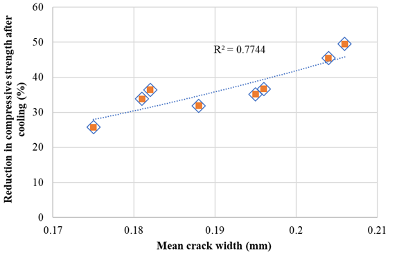
Figure 6.
Relation between reduction in compressive strength and mean crack width after cooling.
3.4. Black Pixel Analysis (BPA) (for air re-curing period)
After cooling, sizes and numbers of cracks increased on the heated surfaces of concrete specimens probably due to expansive CaO rehydration. Therefore, surface pictures of specimens were captured during the first week of air re-curing and these pictures were evaluated in image analysis software in order to evaluate the relation between crack development rate and reduction in compressive strength during air re-curing period. Accordingly, BPA rates of air re-cured concrete specimens were calculated (as explained in Section 2.5) to monitor damage development and these values were compared to differences in compressive strength values after air re-curing period as shown in Table 5.
Table 5. Residual compressive strength and BPA values.
Group
X-Group1 (MPa)
Z-Individual2 (MPa)
(Z-X)/X (%)
BPA Rate (Dayˉ¹)
C00
Spalling was observed. BPA was not examined.
C0S
Spalling was observed. BPA was not examined.
C0P
36.9
20.1
- 45.5
0.187
C0H
36.7
24.6
- 32.8
0.056
CA0
35.5
22.2
- 37.5
0.087
CAS
34.9
25.6
- 26.9
0.087
CAP
25.3
21.2
- 16.1
0.007
CAH
27.2
24.3
- 10.5
0.019
X-Group¹ Represents average residual strength value of 3 specimens after cooling
Z-Individual² Represents individual residual strength value of monitored specimen after air re-curing
Individual compressive strength value of monitored specimen (air re-cured for 28 days following cooling period and tested at the end of this 28-day period) and average compressive strength value of 3 specimens tested after cooling (as an initial strength value before air re-curing period) were used to calculate the change in compressive strength during air re-curing period.
After comparison a scatter gram was obtained as shown in Figure 7 and it showed that there was a logarithmic relation between changes in compressive strength and BPA rates. Calculated R² value for all set of data was 0.77. This rate can be increased by using advanced photographing techniques, by analyzing in specific software, by increasing sample size etc. For example, air voids on the surface of the specimens influence the total amount of black pixels. If the effect of air voids is somehow eliminated more accurate BPA rates can be obtained.
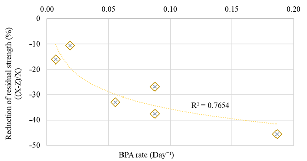
Figure 7.
Black pixel analyses results.
4. Conclusions
In this study, disintegration of various kinds of concrete under air re-curing regime was investigated. BPAs were conducted on air re-cured specimens and the relation between crack development and reduction in compressive strength were evaluated. And the conclusions given below can be drawn regarding to the obtained results limited to the specimen geometry (cubic shape 15by15by15 cm)
5. Acknowledgements
The authors gratefully acknowledge the financial support of Boğaziçi University Research Fund [Project Code 14A04D2]. The support of AKÇANSA Cement and BASF-YKS Construction Chemicals is also acknowledged. The authors also would like to thank Ümit Melep, Bilge Uluocak and Melike Babucci for their support during experimental measurements. The first author is grateful for the financial support given by The Scientific and Technical Research Council of Turkey (TÜBİTAK).
References
Akca, A. H., Özyurt, N. (2013). High performance concrete under elevated temperatures. Construction and Building Materials. 44:317-328. https://doi.org/10.1016/j.conbuildmat.2013.03.005
Alonso, C., Fernandez, L. (2004). Dehydration and rehydration processes of cement paste exposed to high temperature environments. Journal of Materials Science. 39:3015-3024.
Chang, Y. F., Chen, Y. H., Sheu, M. S., Yao, G. C. (2006). Residual stress-strain relationship for concrete after exposure to high temperatures. Cement and Concrete Research. 36 (10):1999-2005. https://doi.org/10.1016/j.cemconres.2006.05.029
Ingham, J. P. (2009). Application of petrographic examination techniques to the assessment of fire-damaged concrete and masonry structures. Materials Characterization. 60 (7):700-709. https://doi.org/10.1016/j.matchar.2008.11.003
Lin, W. M., Lin, T. D., Powers-Couche, L. J. (1996). Microstructures of Fire-Damaged Concrete. ACI Materials Journal. 93 (3):199-205.
Mendes, A., Sanjayan, J. G., Collins, F. (2011). Effects of slag and cooling method on the progressive deterioration of concrete after exposure to elevated temperatures as in a fire event. Materials and Structures. 44:709-718. https://doi.org/10.1617/s11527-010-9660-2
Poon, C. S., Azhar, S., Anson, M., Wong, Y. L. (2001). Comparison of the strength and durability performance of normal- and high-strength pozzolanic concretes at elevated temperatures. Cement and Concrete Research. 31 (9):1291-1300. https://doi.org/10.1016/S0008-8846(01)00580-4
Yüzer, N., Aköz, F., Dokuzer Öztürk, L. (2004). Compressive strength-color change relation in mortars at high temperature. Cement and Concrete Research. 34 (10):1803-1807. https://doi.org/10.1016/j.cemconres.2004.01.015