
| Study Case | https://doi.org/10.21041/ra.v10i2.467 |
Control of reinforcement concrete in pile caps over steel piles - Case study
Controle do concreto de reforço de blocos de fundação sobre estacas metálicas - Estudo de caso
Control del hormigón de refuerzo de encepados de cimentación sobre pilotes metálicos - Estudio de caso
1 PhD Engenharia, São Paulo, Brasil.
2 Professor Titular da Escola Politécnica da USP, PhD Engenharia, São Paulo, Brasil.
* Contact Author: ricardo.boni@concretophd.com.br
Reception: March 15, 2020.
Acceptance: August 11, 2020.
Publication: Septiembre 01, 2020.
| Cite as: Boni, R., Helene, P. (2020), "Control of reinforcement concrete in pile caps over steel piles – Case study", Revista ALCONPAT, 10 (3), pp. 336 – 349, DOI: https://doi.org/10.21041/ra.v10i2.467 |
Abstract
This paper presents a case study about the challenges and good building practices involved in the execution of structural reinforced concrete pile caps over steel piles. The structural reinforcements were carried out in a project with 3 residential towers of approximately 30 floors each, located on the seafront. As a result, it was observed that mix design to define the type and characteristics of concrete, prototype event, particularities of the construction site, executive procedures employed, as well as the systematic monitoring and control of concreting events and other constructive stages were determining factors to promote the safety and quality of reinforcement services in accordance with the assumptions and design requirements.
Keywords:
structural reinforcement,
pile caps,
concrete.
Resumo
Este artigo apresenta um estudo de caso sobre os desafios, as engenhosidades e as boas práticas de construção envolvidas na execução de reforços estruturais de blocos de fundação de concreto armado sobre estacas metálicas. Os reforços estruturais em questão foram realizados em um empreendimento com 3 torres residenciais de aproximadamente 30 pavimentos tipo cada, localizado próximo da orla marítima. Como resultado, observou-se que um estudo prévio de dosagem para definição do tipo e características do concreto a ser utilizado, execução de evento protótipo de concretagem, particularidades do canteiro de obras, definição prévia dos procedimentos executivos empregados, bem como o acompanhamento e o controle sistemático dos eventos de concretagem e das demais etapas construtivas foram fatores determinantes para promover a segurança e a qualidade dos serviços de reforço em conformidade com as premissas de projeto.
Palavras-chave:
reforço estrutural,
blocos de fundação,
concreto.
Resumen
Este artículo presenta un estudio de caso sobre los desafíos, el ingenio y las buenas prácticas de construcción involucradas en la ejecución de refuerzos estructurales de encepados de fundación de hormigón armado sobre pilotes metálicos. Los refuerzos estructurales en cuestión se llevaron a cabo en un proyecto con 3 edificios residenciales de aproximadamente 30 pisos cada uno, ubicados cerca del paseo marítimo. Como resultado, se observó que un estudio previo de dosificación para definir el tipo y las características del hormigón a ser utilizado, la ejecución de un hormigonado prototipo, las particularidades del sitio de construcción, la definición previa de los procedimientos de ejecución empleados, así como el monitoreo y el control sistemático de los hormigonados y otros procedimientos de construcción fueron factores determinantes para promover la seguridad y la calidad de los servicios de refuerzo de acuerdo con las premisas de diseño.
Palabras clave:
refuerzo estructural,
encepados de fundación,
hormigón.
1. Introduction
Located on a plot of over 7.000 m², about 250 m from the seafront in the city of Vitória, ES, Brazil. The project consists of 3 residential towers with a total of 166 units. Tower 1 has 33 floors and Towers 2 and 3 have 31 floors each.
The residential complex, whose construction was completed at the end of year 2010, also has two garage floors under the projection of the towers and the area of common use, both located above the water level, that is, without the need to use pressure slab. The structural reinforcement of pile caps of residential towers project was carried out in the first semester of 2018, between the months of January and May, due to non-conformities observed in the structure construction, verified during the partial collapse occurred in the area leisure facilities.
This paper presents the studies, the tests, the ingenuity, the good engineering practices, the procedures employed in the execution of these reinforcements and the activities developed, with emphasis on the quality control of concrete.
2. Basic data of reinforcement project and concrete mix design
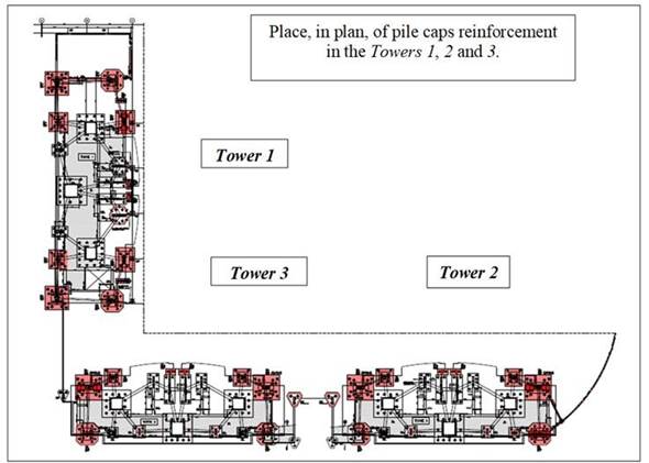
The structural reinforcement project for the residential tower pile caps was prepared according the recommendations of standard ABNT NBR 6118:2014. This project includes the reinforcement of 20 structural elements, as highlighted in Figures 1 and 2, which presents the structural reinforcements executed in floor plan and in perspective (highlighted in red), respectively.
 |
||||
| Figure 1. Location detail, in plan, of pile caps structural reinforcement in the residential towers. | ||||
 |
||||
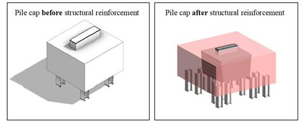
| Figure 2. Generic detail in perspective from the pile caps structural reinforcement (before and after). | ||||
In Figure 2, it is noted that additional steel piles were driven into the periphery of existing piles caps. In total, 152 piles shape W200x86 and W250x115 were spiked, with a workload of 194tf and 258tf, respectively. Execution lengths ranged from 20 to 22 meters deep. The foundation reinforcement project was developed based on the requirements of standard ABNT NBR 6122:2010.
The compressive strength of concrete specified for the reinforcement of elements was fck ≥ 40MPa, modulus of elasticity Ec ≥ 32GPa, for a tension corresponding to 14MPa (0,35 fck), with a maximum w/c ratio of 0,50. This specification meets the strong environmental aggressiveness class (CAA III) required in project, according to sub-items 6.4 "Environmental aggressiveness" and 7.4 "Quality of cover concrete" of standard ABNT NBR 6118:2014.
Thus, based on design assumptions, availability of raw materials in the region, needs and particularities of the construction site a concrete mix design study was developed. For this study, the standards ABNT NBR 12655:2015 and ABNT NBR 15823:2017 Parts 1 to 6 related to self-compacting concrete were used. In addition to these standards, it also served as a reference the guidelines of the IBRACON method (TUTIKIAN, B.; HELENE, P., 2011) for the development of a self-compacting concrete, with SFII spreading class, which is shown in Table 1.
| Table 1. Self-compacting concrete mix design, dry material weight, fck ≥ 40MPa by 28 days of age for 1m³ of concrete | ||||||||||||
| Self-compacting concrete mix design, spreading class SFII | Design for fck 40MPa | |||||||||||
|---|---|---|---|---|---|---|---|---|---|---|---|---|
| cement consumption by m³ (CP III-40-RS) | 425kg | |||||||||||
| water/(cement+addition) ratio | 0,43 | |||||||||||
| water | 183kg | |||||||||||
| fine sand | 329kg | |||||||||||
| medium sand | 494kg | |||||||||||
| crushed stone 0 | 960kg | |||||||||||
| polyfunctional additive | 2,5kg | |||||||||||
| superplasticizer additive¹ | 1,5kg | |||||||||||
| (1) Fully added to the mixing central. Only in the case of eventual spreading corrections, it was allowed the additional use of this additive in construction site, in small quantities, depending on the need. | ||||||||||||
The visual aspect of concrete in question can be seen in Figures 3, 4 and 5, which show the spreading tests, passing skill in J ring and passing skill in box L, performed in accordance with standards ABNT NBR 15823-2:2017, ABNT NBR 15823-3:2017 and ABNT NBR 15823-4:2017, respectively. Still, in Figure 3, it is also possible to observe the visual stability index (IEV) of concrete that was developed especially for the structural reinforcement of pile cap on this project.
 |
||||
| Figure 3. Detail of spreading test performed in the laboratory during the dosage study. | ||||
 |
||||
| Figure 4. Detail of passing skill test through box L, performed in the laboratory during the dosage study. | ||||
 |
||||
| Figure 5. Detail of passing skill test through the J ring, performed in the laboratory during the dosage study. | ||||
In order to minimize possible non-conformities related to compressive strength and elasticity modulus of concrete, it was agreed among stakeholders that, during the events of concreting the structural reinforcement, no water would be added to the balloon of the mixer truck after it left the mixing central (where the amount of mixing water is properly controlled by hydrometers).
Therefore, at the construction site, after conducting the acceptance tests (spreading measured by slump flow test), if there was a need to correct the spreading of concrete, this would be done only by means of an additive, through technical support consultant.
Also, prior to the concreting of reinforcement of pile caps, a prototype event (simulation in a concrete mixer truck) was carried out to evaluate the behavior of concrete studied in the laboratory under field conditions. It was observed that the time to transport the concrete from the mixing central to the construction site was approximately 25 minutes, a distance of 9,6 km and that the time to cast the concrete was, at most, 30 minutes, by concrete mixer truck.
At the opportunity of prototype concreting event, cylindrical specimens were also molded for compression strength tests at 3, 7, 14, 28 and 45 days of age and elasticity modulus at 28 days, as shown in Figure 6.
 |
||||
| Figure 6. Detail of the molding of cylindrical specimens in the prototype concreting event for tests of resistance to compression and modulus of elasticity. | ||||
Based on favorable results of resistance to compression and modulus of elasticities obtained in dosage study carried out in laboratory and in the mentioned prototype event, the services for concreting the structural reinforcement of pile caps were initiated according to the steps detailed below in the sub-item Executive Procedures.
3. Executive procedures
The executive procedures adopted in this case study are based on the Brazilian standards in force, mainly the standard ABNT NBR 14931: 2004 and on good engineering practices.
The services started with the driving of steel piles in the regions located around the pile caps to be reinforced, as shown in the perspective of Figure 2. These piles have depths ranging from 20 to 22 m and were spiked by adapted piles, positioned between slabs, as shown in Figure 7.
 |
||||
| Figure 7. Detail of the adapted pile spiking positioned between slabs to perform the spiking services of the structural reinforcement piles. | ||||
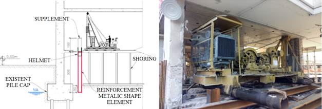
Due to the difficulty of access, the dimensions of spiking equipment and the existing interference at the site, for the execution of this reinforcement step, some additional services were necessary, including:
- previously propping the ground floor slab, under which the spiking equipment were supported;
- adapt all the spiking equipment, as the height of the pile tower is much greater than the distance between slabs (ceiling height);
- execute localized demolitions and holes in the ground floor slab to allow for the spiking of steel piles;
- divide previously the steel piles (in lengths ranging from 2 to 4 m) to allow the plumb position of shape at the spiking point;
- use a supplement (above the protective helmet of the pile head) in order to help spike the shape.
In this way the metal segments piles were spiked and immediately welded to the subsequent segments, as the services progressed. Figure 8 illustrates the execution of services and the piles spiked in the periphery of one of pile caps. In the latter case, for better visualization, the image registration made after excavating the pile cap surroundings.
 |
||||
| Figure 8. Detail of execution of spiking services (on the left) and of steel piles spiked around the pile cap to be reinforced (on the right). | ||||
After spiking all the piles of a certain pile cap, the excavation was carried out. For such, a system was installed with water level lowering pumps located in the region surrounding the pile cap (this system would be deactivated only after concreting and backfilling). The excavation was carried out with small equipment or, in most cases, manually, again due to interference and difficult access conditions.
In the sequence, the thin concrete coverage with 5 cm thickness was executed, as well measure of dimensions of existing piles caps, through the topography, possible eccentricities of existing piles (under load), as shown in Figure 9.
 |
||||
| Figure 9. Detail of measurement dimensions of existing pile cap and of the steel piles, after excavation and execution of thin concrete. | ||||
After this stage, the services of cutting the piles began, whose top should be 35 cm above the lower level of reinforcement pile cap, and preparation of lateral surfaces of pile cap, as shown in Figure 10. In this stage, chamfers and ridges were made in the edges and lateral surfaces of pile caps, in addition to chipping of all faces, except the lower one, according to structural design requirements.
 |
||||
| Figure 10. Detail of execution of chamfers and ridges in the edges and lateral surfaces of pile cap. | ||||
The execution of chamfers and ridges on the sides of existing blocks were essential and very important, since they aimed to guarantee the quality of concreting joint in the old concrete/new concrete interface (to be launched) and to collaborate in the transmission of efforts. The execution of chamfers on the lateral edges provided a cone-like geometry (or stopper) that dispensed the verification of adherence between the existing block and structural reinforcement.
It is recorded that the ridges were made 3 cm deep along all the lateral surfaces and the chamfers of lateral edges with dimensions varying from 0 cm (on the upper face) to 15 cm (on the lower face of pile cap), as evidenced in Figure 11.
 |
||||
| Figure 11. Detail of project indicating positioning of ridges and chamfers. | ||||
The Figure 12 shows the pile cap after the completion of concrete surface treatment services.
 |
||||
| Figure 12. Detail of the surface treatment of pile cap. Detail of the project (left) and the situation “building site” (right). | ||||
After preparing the surface, the structural reinforcement services started by a specialized company and certified labor began, through monitoring and verification of services, with regard to positioning, gauges, number of bars and other steps involving quality control, including the use of multi-support spacers on sides and bottom of pile cap, in order to guarantee the specified coverage of project (40 mm).
It is recorded that that the steel bars used in the structural reinforcement of pile caps (gauges 25 mm, 20 mm, 16 mm and 12,5 mm) were delivered to the work cut/folded and properly identified. Figure 13 shows the execution of reinforcement frame services for the pile caps.
 |
||||
| Figure 13. Detail of execution of reinforcement frame services of pile caps. | ||||
Upon verification of frame and release by the engineering staff, initiated the assembling the wooden forms and shoring, as shown in Figure 14. All of these services were also monitored and checked for flatness, plumbs, dimensions, locking system and water tightness.
 |
||||
| Figure 14. Detail of the formwork of structural reinforcement pile caps. | ||||
Finishing the structural reinforcement services, the concreting of reinforcement structural element was carried out, through the use of self-compacting, pumped concrete, as detailed in item 2 “Basic Data of Reinforcement and Concrete Design” of this paper. Figure 15 shows the visual aspect of concrete observed in the field.
 |
||||
| Figure 15. Visual aspect of self-compacting concrete used to reinforce structural pile caps. | ||||
At this stage, it was indispensable that the concrete was cast at a low speed to avoid trapping air on the lower surface of pile cap, thus avoiding possible hidden concrete failures. In order to avoid non-conformities of this nature, the concrete from the lower portion of pile cap was launched slowly, on only one side of pile cap, and moderately vibrated with immersion vibrators with a diameter needle of 40 mm.
It is important to note that the treated surface of existing pile cap, the region of interface with the new concrete, was previously cleaned with a pressurized water jet, in order to remove all dust, powdery material or any other type of contaminant. The self-compacting concrete was cast on a clean surface in a dry saturated condition.
The Figure 16 shows the concreting event of reinforcement of one pile cap, performed with self-compacting concrete, respecting the premises mentioned in the previous paragraph.
 |
||||
| Figure 16. Detail of the concreting of reinforcement of pile cap, made with self-compacting concrete. | ||||
On the receipt of concrete at building site, spreading tests (slump flow test) were carried out on all concrete mixer trucks, by specialized laboratory, according to recommendations of standard ABNT NBR 15823-2:2017. In these cases, the spreading class, the visual stability index obtained, as well as the visual aspect of concrete, which should be cohesive, with no exudation or apparent segregation were observed and analyzed. As previously noted, in the case of need for correction spreading, only superplasticizer additive was used, under no circumstances was the spreading corrected by adding water on the construction site.
In addition to the receiving tests mentioned in the previous paragraph, whenever possible, technical visits were made to the concrete batching central, in order to monitor the concrete production procedures, with regard to the control of inputs, tests to determine the moisture content of fine aggregates, dosage, mixture and other steps.
In order to minimize the risk of fissuration, after concreting, the side forms were maintained for a period of 3 days in order to avoid the surface evaporation of water. In addition, the top face of pile cap was always kept moist, by aspersion potable water, in order to guarantee ideal curing conditions.
Subsequently, after removing the formwork, thorough inspections were carried out on all surfaces of reinforcement performed and in the regions of new concrete/old concrete interface. It is registered that no type of non-conformity was found related to concreting failure, fissures etc.
Figure 17 shows the visual aspect and the surface finish of concrete in the hardened state applied in the reinforcement of pile caps.
 |
||||
| Figure 17. Detail of the visual aspect and the surface finish of concrete of reinforced pile caps. | ||||
Soon after the inspection, the blocks were released to be grounded. For this, a mechanical compactor was used.
With regard to technological control of concrete, 6 specimens were molded per concrete mixer truck to perform compression resistance tests at the ages of 7, 28 and 45 days (2 per age), using the total sampling criterion, according to item 6.2.3.1 “Control of concrete by total sampling (100%)” of standard ABNT NBR 12655:2015.
The specimens were molded, stored and transported in accordance with the requirements of standard ABNT NBR 5738:2015. It is noteworthy that the specimens molded for the 45 days of age would only be tested in the case of identification of non-conformities related to the compressive strength at 28 days. The results obtained are detailed below.
4. Results obtained
Considering the executive procedures described above and the good engineering practices adopted, the results obtained are presented below, regarding the integrity and quality of concrete used.
After concreting and carrying out visual inspections on all reinforcements of pile caps, it was found that they did not show any fissures resulting from the retraction phenomenon or any other type of material failure that could compromise their integrity, its durability and service life of structure.
Regarding the technological control of concrete applied in the structural reinforcement of pile caps on residential towers, Figure 18 graphically presents the results of concrete compressive strength at 7 and 28 days of age of 66 concrete mixer trucks (100% sampling), in the form of chart
As can be seen, the average resistance obtained was 45,2MPa, standard deviation of 2,9 MPa, coefficient of variation equal to 6,4% and with extreme values ranging from 40,7 MPa (minimum) to 53,9 MPa (maximum). Considering the resistance specified in the project, it is registered that all results are in compliance.
 |
||||
| Figure 18. Concrete individual chart of values fck 40MPa, self-compacting used in the structural reinforcement of pile caps. | ||||
5. Final considerations
This article aimed to highlight that simple recommendations coherent with the current standardization and good constructive practices, previous studies, as well as the systematic control and technical monitoring of activities that preceded and followed the concreting events, were sufficient to promote an upstanding structural element and a satisfactory final result in accordance with the project requirements.
6. Acknowledgements
Special thanks are due to the professionals from companies and offices responsible for the preparation of Geoconsult foundation project, for the structural reinforcement project França & Associados, for the construction Cyrela and for the supply of concrete Concrevit, which together with the consulting of PhD Engenharia made this possible achievement with quality.
References
Associação Brasileira de Normas Técnicas. (2014). NBR 6118: Projeto de estruturas de concreto - Procedimento. Rio de Janeiro.
Associação Brasileira de Normas Técnicas. (2004). NBR 12655: Concreto de cimento Portland - Preparo, controle, recebimento e aceitação - Procedimento. Rio de Janeiro.
Associação Brasileira de Normas Técnicas. (2004). NBR 14931: Execução de estruturas de concreto - Procedimento. Rio de Janeiro.
Associação Brasileira de Normas Técnicas. (2010). NBR 6122: Projeto e execução de fundações. Rio de Janeiro.
Associação Brasileira de Normas Técnicas. (2015). NBR 5738: Procedimento para moldagem e cura de corpos de prova. Rio de Janeiro.
Associação Brasileira de Normas Técnicas. (2017). NBR 15823-1: Concreto autoadensável. Parte 1: Classificação, controle e recebimento no estado fresco. Rio de Janeiro.
Associação Brasileira de Normas Técnicas. (2017). NBR 15823-2: Concreto autoadensável. Parte 2: Determinação do espalhamento, do tempo de escoamento e do índice de estabilidade visual - Método do cone de Abrams. Rio de Janeiro.
Associação Brasileira de Normas Técnicas. (2017). NBR 15823-3: Concreto autoadensável. Parte 3: Determinação da habilidade passante - Método do anel J. Rio de Janeiro.
Associação Brasileira de Normas Técnicas. (2017). NBR 15823-4: Concreto autoadensável. Parte 4: Determinação da habilidade passante - Método da caixa L e da caixa U. Rio de Janeiro.
Helene, P., Terzian, P. (1993), “Manual de dosagem e controle do concreto”. PINI/SENAI, São Paulo, Brasil, p. 349.
Tutikian, B., Helene, P. (2011), “Dosagem dos Concretos de Cimento Portland” In. Geraldo C. Isaia (Org.). Concreto: Ciência e Tecnologia. 1 ed. São Paulo: Ibracon, 2011, v. 1, p. 415-451.