| Applied Research | https://doi.org/10.21041/ra.v11i2.454 |
Damage assessment proposal for two bridges located on Highway No. 14 in the State of Sonora México by using stiffness invariant as global comparison parameter
Proposta de avaliação de danos para duas pontes localizadas na rodovia No. 14 no estado de Sonora, México, usando a variável de rigidez como parâmetro de comparação global
Propuesta de evaluación de daño para dos puentes ubicados en la carretera No. 14 en el estado de Sonora México usando invariante de rigidez como parámetro global de comparación
G. Ramos-Torres1 *, H. Navarro-Gómez2, E. Perez-Isidro2, J. Gautherau-Lopez1, I. Palma-Quiroz2
1 Departamento de Ingeniería Civil y Minas, Universidad de Sonora, Hermosillo, México.
2 Instituto de Ciencias Básicas e Ingeniería, Universidad Autónoma del Estado de Hidalgo, México.
*Contact author: calculista@prodigy.net.mx
Reception: January 16, 2020.
Acceptance: October 23, 2020.
Publication: May 01, 2021.
| Cite as: Ramos-Torres, G., Navarro-Gómez, H., Perez-Isidro, E., Gautherau-Lopez, J., Palma-Quiroz. I. (2021), "Damage assessment proposal for two bridges located on Highway No. 14 in the State of Sonora México by using stiffness invariant as global comparison parameter", Revista ALCONPAT, 11 (2), pp. 89 – 108, DOI: https://doi.org/10.21041/ra.v11i2.454 |
Abstract
The elastic rigidity invariant method is used to obtain the mechanical response of the superstructure of simply supported bridges; it is based on the bridge’s response to the impact of known masses applied on mid span to obtain the maximum displacement that defines the point stiffness. This value is compared with the values of the theoretical curve formed with the stiffness invariants, constructed from the design characteristics of the bridge. The method was implemented in two bridges located on federal highway No. 14 of the State of Sonora Mex., with results according to the damage manifested. The evaluation is the result of a global parameter, obtained in environmental conditions in the absence of wind and at a constant temperature, suitable for the diagnosis of the present structural state, having limitations on bridges with screw cross sections.
Keywords:
bridges,
superstructure,
impact,
mechanical response,
stiffness.
Resumo
O método da variável de rigidez elástica permite obter a resposta mecânica da superestrutura da ponte; baseia-se na resposta ao impacto de massas conhecidas aplicadas ao centro do vão (luz) para obter o deslocamento máximo que define a rigidez do ponto, este é comparado com os valores da curva formada com as variáveis de rigidez, construídos a partir do características do projeto estrutural da ponte. O método foi implantado em duas pontes localizadas na rodovia federal nº 14 do Estado de Sonora Mex., com resultados compatíveis com os danos manifestados. A avaliação é qualitativa a partir de um parâmetro global, obtido em condições ambientais na ausência de vento e a temperatura constante, adequado para o diagnóstico do estado estrutural presente, havendo limitações em pontes esconsas.
Palavras-chave:
pontes,
superestrutura,
impacto,
resposta mecânica,
rigidez.
Resumen
El método de la invariante elástica de rigidez permite obtener la respuesta mecánica de la superestructura de puentes; se basa en la respuesta al impacto de masas conocidas aplicadas al centro del claro para obtener el máximo desplazamiento que define la rigidez puntual, éste se compara con los valores de la curva formada con los invariantes de rigidez, construida a partir de las características de diseño del puente. El método se implementó en dos puentes localizados en la carretera federal No. 14 del Estado de Sonora Mex., con resultados acordes a los daños manifestados. La evaluación es cualitativa a partir de un parámetro global, obtenido en condiciones ambientales en ausencia de viento y a temperatura constante, adecuado para el diagnóstico del estado estructural presente, teniendo limitantes en puentes esviajados.
Palabras clave:
puentes,
superestructura,
impacto,
respuesta mecánica,
rigidez.
1. Introduction.
Worldwide, the design and construction of bridges is governed by regional standards and involves a series of studies prior to their design and construction that are supported by permanent research aimed at reducing the risk of collapse or premature failure; These standards include operational maintenance protocols, however, failures and even collapses frequently occur. A sample of 384 collapsed bridges worldwide in the period from 1944 to 2004 revealed that 28% collapsed due to natural causes, 21% due to design errors, 18% due to impact, 10% due to overloading, 10% due to human error, 10% from unknown causes, 2% from corrosion and 1% from vandalism (Imhof, 2004). The greatest difficulty in the inspection of bridge structures is obtaining a damage index for making maintenance, repair, or replacement decisions.
A summary of some methods to obtain mechanical response in bridges is presented below: For non-linear ranges, the dynamic plastic hinge method was proposed; It is used to obtain the modal load-deformation curve from a one-degree-of-freedom model. The structure is subjected to the acceleration of a given earthquake until the maximum response is obtained in which the plasticization of a previously proposed ball joint is reached, the system becoming a mechanism; This simplified method allows visualizing the ductility demand of the structure (E. Maldonado, et al. 1998). By means of numerical methods, an amplification factor can be obtained that considers the dynamic effects applicable to the mechanical design elements of continuous bridges, considering flexible beams and mobile loads damped by the suspension of the analyzed type trucks. motion equation of the bridge is assumed in forced vibration by the equation of motion of the test truck that has a point of application of load per axle, the beam is idealized as a series of masses concentrated in discrete intervals uniformly distributed in its total length and the effects of truck loading are computed on the front axle; This procedure makes it possible to obtain an impact factor for the mobile load, also known as the dynamic amplification factor, which results from the displacement curves generated for both static and dynamic loads.
The procedure allows to include a friction factor due to the participation of the suspension of the analyzed truck (N. Munirudrappa et al. 1999). The method frequency response functions consist of obtaining a structural characteristic matrix, which is a function of mass, damping and its stiffness. It is obtained by inverting the frequency vector functions cofactors matrix of the motion equation´s Fourier transforms and is known as frequencies response functions matrix. This matrix has only the structure properties and is independent of the excitation, so any change generated in it is due to changes in the constitution of the structure. To obtain the frequency response functions matrix of the displacement vectors and their excitation forces must be known in terms of their Fourier transforms. This is a complex method compared to the modal analysis method, since it requires a much greater number of sensors and a large numerical processing that couples the local and global effects.
The sensitivity analysis method consists of obtaining a sensitivity factor that is equivalent to the quotient between the rate of change in frequency and the rate of change in stiffness. This method helps to select the parameters with the greatest impact on the response and to rule out possible errors in the experimental instrumentation, in such a way that it allows to choose the most significant or highest impact values and to visualize the structural elements with the greatest contribution to dynamic effects. Based on this information, it is possible to determine with good precision the points where the sensors should be placed for experimental studies. A group of experimental methods that make use of numerical simulation methods, where numerical methods such as Runge-Kutta, Euler, etc. can be used to solve the differential equations of motion from the Jacobian of the quotient between the rate of change of the forces and the rate of change of the displacements whose real solutions must be negative to guarantee the stability of the method and its integration in time. In short, the finite element method is the most used to solve the motion equations, as it uses discretization and interpolation using functions that are compatible with stresses and strains, considering internal equilibrium, equilibrium at the boundary and the compatibility of deformations of the discrete elements that are solved by direct integration and assembled in linear systems of equations provided that the differential equations are ordinary (Carrión FJ et al. 1999). A model to study the effects of temperature compared to the effects of damage in the change of the natural frequency of a span bridges, using finite element models for box girders and prestressed ASHHTO type girders; The article indicates that the changes in the frequency of the superstructure of a bridge of a clearing due to thermal effects (temporary softening), are similar to the effects of damage accumulated over a long period of time (Balmes Etienne et al. , 2005).
A study was carried out by instrumenting two slab bridges and prestressed girders, both of two independent spans; data was collected by means of acceleration sensors; numerical methods were used to find the spectra of speeds and displacements. Likewise, with an adequate frequency filtering, it was possible to separate the static and dynamic effects of the obtained spectrum; The results evaluation indicates that the impact factors obtained by means of the quotient between the load dynamic effect and the load static effect, under certain mass and speed conditions of the test vehicle, exceed those established in the design codes. (Valdez J. et al. 2008). A comparative analysis to obtain the dynamic response of a reinforced concrete bridge located in Italy using a finite element model with Shell-type elements and the excitation of a typical truck at different speeds.
The theoretical analysis was carried out assuming the non-existence of cracking to ignore the contribution of reinforcing steel in estimating stiffness. The results obtained in the analysis indicated that with a single truck it was not possible to obtain the basic dynamic parameters, so a continuous convoy of trucks was used, offering results more in line with reality; the contrast was performed with the data obtained from the application in the excitation site using an electric vibrator placed in the quarter of the bridge span and placing a series of 17 acceleration sensors to obtain the response in real time. The results obtained in the analysis presented errors ranging from 1% to 46% compared with the frequencies obtained on site, the torsion frequency being the one with the lowest error and that of the fourth bending mode the one with the highest error (Veles H. et al. 2011). A methodology to determine the concrete bridges superstructure fatigue deterioration of the reinforced, using Monte Carlo techniques; The method estimates probabilistically according to the statistical data the number of load cycles and their impact on the stress level, using the most popular damage models that allow an estimate of the crack size to be given. This method is speculative and can be applied with relative ease if the operating statistics of the bridge under analysis are known, however, as it is presented, it does not include factors such as extraordinary loads, or earthquakes and corrosion effects, among others, (Crespo E. et al. 2013).
The results of the application of the environmental vibrations method (spectral ratio) applied to the instrumentation of a post-tensioned bridge that allowed them to evaluate the superstructure’s present state, the instrumentation results were compared with the results of the structural model made using commercial software. (Viviescas Al. et al. 2017).
2. Methodology.
Of the bridge infrastructure on federal highways in Mexico, 57% are built of reinforced concrete, followed by 28% built of prestressed concrete, 7% built in steel and concrete, 6% in structural steel, 1% in masonry and 1% in 3dsalb system (IMT-2014). According to the statistics of the Mexican Institute of Transportation, the largest number of bridges is built using reinforced concrete, so the present work studies two reinforced concrete bridges; one based on solid slabs and the other built on beams and slabs with diaphragms of reinforced concrete.
The present work consists of the application of a methodology that uses global parameters; includes the real present point stiffness of the structure, which is obtained from field measurements on the real structure; the value obtained is compared with the stiffness value obtained from the design parameters of the bridge that result from the stiffness invariant function; the quotient between these values corresponds to the residual capacity of the structure, allowing a damage index to be obtained.
2.1. General concepts.
The structural mechanical behavior under service loads depends on the level of efforts achieved and the number of repetitions or load cycles; Factors such as deterioration, corrosion, fatigue and / or an increase in the level of service loads, can generate permanent damage that modify the conditions of its mechanical response. Design considerations for the structural performance is based on elastic linear mechanical behavior and the structure is considered healthy if this behavior is preserved. When the accumulated damage modifies this behavior, non-linear behavior begins where the proportion between the displacements and the applied forces is no longer constant; It is under this basic principle that the proposed method offers information on the present structure state.
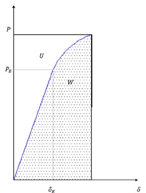
Figure 1 presents the structural system’s mechanical behavior under monotonic load with gradual load increase; First, a straight line can be seen beginning at the origin and reaching the coordinates (δE, PE); (δE) corresponds to the displacement up to the linear elastic limit and (PE) to the load in the same limit; the curved part indicates that the structural system has a non-linear behavior.
The proposed method considers that if three increasing point loads are applied, a load-displacement graph is obtained that describes a mechanical behavior like the real one; From the applied load increments, joining the coordinates of the three points, two lines are obtained that have the same slope if working in a linear range or secant to the real stress-strain curve of the structure if the work is in a non-linear range. If the load increments are small, the upper and lower areas of the real curve are remarkably like the upper and lower areas of the graphs of the lines obtained, reducing the error of the method. The areas described provide a way to measure the damage.
 |
||||
| Figure 1. Load displacement relationship | ||||
2.2. Damage assessment.
Figure 1 is divided into two regions, a lower one whose area corresponds to the work W that was produced during the loading process and an upper one whose area corresponds to the deformation energy U stored by the structure, which allows it to recover its original shape if the load is removed fully or partially. When the structural mechanical behavior is linear elastic, the work and the deformation energy have the same magnitude, which implies that the structure can recover its original configuration if the loads are removed; if the behavior is non-linear, the values of the work done and the stored deformation energy are different, which implies that, when the load is removed, the structure will partially recover its configuration. Disregarding the energy generated in the form of heat, if the structure has non-linear behavior, the stored deformation energy is less than the work done by the system; This consideration is applicable in reinforced concrete structures.
There are some semi-empirical expressions to evaluate the damage in reinforced concrete structures obtained from experimental tests; One of the expressions that allows obtaining a damage index considering the slope of the elastic part of the discharge curve, is defined by the following expression:
 |
(1) |
Where d is a damage index, Z is the slope of the discharge branch elastic part and Z0 is the slope value of the initial elastic branch (Perdomo M. E. et al, 2006). For elastic behavior, the expression (1) has a null value and for inelastic behavior near the failure point the value is close to unity. With this expression, an energy restitution curve for the test elements can be obtained and the damage index generated prior to failure is achieved, the difficulty of its use entails carrying out experimental tests for each type of structural element.
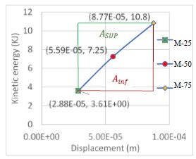
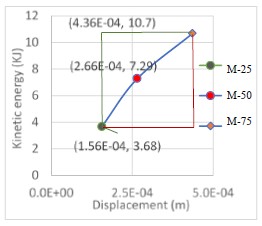
According to the proposal of the present work, the real deformation is obtained from the acceleration-time spectrum double integration that results from the impact applied to the real structure with known masses and their free fall heights, only considering the maximum amplitude of the displacement; from these values a kinetic energy vs. displacement graph can be constructed; the upper area of the graph is identified with area Asup, analogous to the deformation energy density U and the lower region is identified with area A inf,, analogous to the density of work done W. The quotient of these two quantities ∆k, is a measure of damage based on the energetic change due to the decrease in the rigidity of the system because of damage and is applicable to the major test load.
 |
(2) |
2.3. Invariant elastic stiffness.
It is formed with the stiffness values below the limit of proportionality along the length of a structural element. In (3) K, corresponds to the theoretical design stiffness value, F corresponds to the applied force and δ is the resulting displacement.
 |
(3) |
If the virtual work principle is applied and considering only the contribution of the bending moment, the expression for the stiffness at a point corresponds to (4).
 |
(4) |
If the value of the force F is kept constant throughout each point of the structure, under the limit of proportionality the stiffness curve is obtained and has the character of invariant at each point.
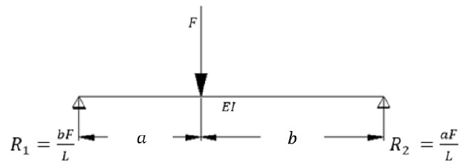
According to figure 2, if F is applied in the coordinate X = a, it is necessary to determine the displacement δ and the stiffness K (a).
 |
(5) |
 |
||||
| Figure 2. Load displacement relationship | ||||
Once the displacement is known, the stiffness is obtained in the coordinate x = a; considering b = L-a, where (6) is the stiffness invariant applied for beams and (7) the invariant for solid slabs.
 |
(6) |
 |
(7) |
2.4. Measurement of actual point stiffness.
The actual point stiffness is obtained with the maximum displacement that occurs when subjecting the superstructure to impact loads applied to the center of the span; Small masses are used for excitation, which minimally modify the dynamic parameters of the structure. To calculate the impact force FR, the fundamental expressions of clasic mechanics are used, which are described below:
 |
(8) |
g=acceleration of gravity
h=fall height
Since the impact is made in a deformable medium, the magnitude of the force depends on the reaction stiffness; (9) corresponds to the kinetic energy now of impact.
 |
(9) |
m = mass.
From the kinetic energy-displacement graph, as previously mentioned, the upper area of the curve Asup, is analogous to the deformation energy (U) and the lower area A inf, is analogous to the work done (W), so ∆k corresponds to a residual stiffness factor, which with a unit value indicates structural health and any value less than one indicates permanent damage to the structural system.
The residual stiffness factor ∆k (2) is applicable to reinforced concrete structures. It corresponds to the increase in the cracking of the cross section, due to the creep of the reinforcing steel as damage accumulates which is reflected in the decrease of the compression area since the cracking as the steel receives greater deformation, grows in the tension zone. Therefore, the moment of inertia of the cross section is reduced, expressed by ID for its consideration within method (10). To know the value of the present real stiffness, it is required to obtain the effective force when the kinetic energy is zero at the instant of maximum displacement. The value of the real force for each group of impacts is obtained from the use of (11) considering the impact load applied to the center of the span.
 |
(10) |
 |
(11) |
With (12), the actual present stiffness KR is obtained; FR¯ corresponds to the average effective impact force and δ¯ to the average of the displacements measured in the field for each mass.
 |
(12) |
 |
(13) |
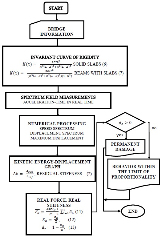
In(13), de is considered a damage index and is a measure of the degradation or decrease in stiffness. in healthy structures the value is null; for collapse it is close to unity and depends on the characteristics of each structure. In the proposed method, the system preload corresponds to the permanent load of the structure, which can be of the order of up to 85% of its total capacity. This allows the use of small load increments to obtain deformations in advanced areas of the hysteresis stress strain curve envelope. Figure 3 shows the methodology flow diagram used for the studies case. First of all, it is necessary to have the project structural plans. For field measurements, a mass system is used that during the impact is coupled to the movement of the structure to avoid rebound. Preferably, the amount of mass for each group of tests should have proportional values, in order to facilitate the corresponding calculations. It is very important that when choosing the test masses, the structure response acceleration is at least 20% below the maximum acceleration limit of the sensor and that the acceleration values for each different mass have sufficient discrimination for numerical processing. The rest of the activities are presented in the same figure.
 |
||||
| Figura 3. Flow diagram, Stiffness invariant method. | ||||
3. Study cases.
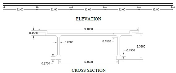
The instrumented bridges are located on federal highway 14, Hermosillo-Moctezuma, in the state of Sonora, México; one of the bridges bears the name of "El Testarazo" figure 4, which is located at km 23 + 900. The bridge has a superstructure made of three reinforced concrete slabs, simply supported on abutments made up of reinforced concrete walls. The other instrumented bridge is called "El Gavilán" figure 5; The super structure is formed by a system of reinforced concrete beams, slabs, and diaphragms, with a section skewed at 48 ° from its transverse direction, located at Km 60 + 100 of the same roads.
3.1. Information on the case studies.
 |
||||
| Figure 4. “El Testarazo” bridge superstructure Geometry (Dimension m). | ||||
 |
||||
| Figure 5. “El Gavilán” bridge superstructure geometry (Dimension m). | ||||
The cross sections geometric properties were obtained under the transformed section criterion, and the project data were obtained from the Type Project of Reinforced Concrete Elements, Part I, published by the now extinct SAHOP.
| Table 1. Geometric properties transformed section of bridges (m). | ||||||||||||||
| Bridge | bw | hf | bf | n | As(m2) | d | kd | Icrt(m4) | A(m2) | |||||
|---|---|---|---|---|---|---|---|---|---|---|---|---|---|---|
| Testarazo | 5.2 | 0.30 | 10.0 | 8.796 | 0.035 | 0.645 | 0.1858 | 0.1108 | 2.95 | |||||
| El Gavilán | 1.08 | 0.18 | 7.5 | 8.796 | 0.0386 | 2.182 | 0.481 | 1.199 | 2.89 | |||||
For the bridge “El Testarazo” EI = 2,595 MN - m² (for solid slab stiffness); for the El Gavilan bridge EI = 28,082 MN - m² (for beam stiffness). With these values the stiffness curve was obtained. In both cases, only bending effects are considered. The concrete elasticity modulus value used was E = 23.414 Mpa, based on the expression E = 15100 √(ƒc')(Kg/cm2).
3.2. Stiffness invariant curve.
Figures 6 and 7 show the cofactors graphs corresponding to the stiffness invariants, obtained from (4) for the “El Gavilán” bridge and from (5) for El Testarazo bridge. The KE project stiffness values at the superstructure mid span are presented in table 2; said values result from the product of the cofactors illustrated in Figures 6 and 7 with the respective EI´s values.
| Table 2. Stiffness values under the limit of proportionality. | ||||||||||||||
| Bridge | “El Testarazo” | “El Gavilán” | ||||||||||||
|---|---|---|---|---|---|---|---|---|---|---|---|---|---|---|
| KE(MN/m) | 66.432 | 41.237 | ||||||||||||
 |
||||
| Figure 6. “El Testarazo” bridge stiffness cofactor. | ||||
 |
||||
| Figure 7. “El Gavilán” Bridge Stiffness Cofactor. | ||||
3.3. Procedure to obtain the structure real stiffness.
The field measurements were made using a structure for lifting and unloading the excitation masses. The equipment consists of a quadruped skeleton that allows the masses to be raised by means of a 2250 N capacity winch; the container holding mechanism is made up of an electromagnet with a capacity of 6 KN that enables the excitation mass to be clamped by means of a safety hook with a torsional freedom degree (fig. 8).
 |
||||
| Figure 8. General appearance of the field test equipment. | ||||
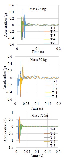
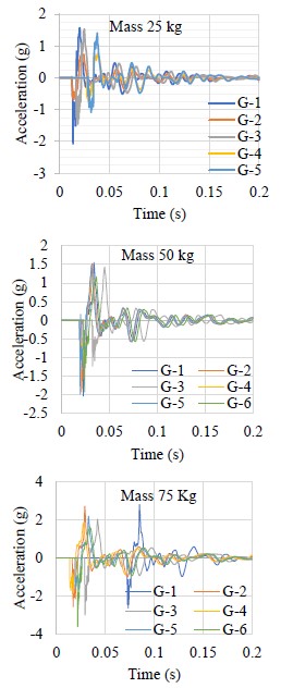
Sand containers were used, with plastic behavior during the impact, to avoid rebound; Three sacks of 25, 50 and 75kg capacity were manufactured, which were filled up to the test mass; the impact was achieved by raising the sacks to an average height of 1.50m, subsequently, the electromagnet electrical flow that held them was interrupted to release them and produce the impact on the bearing bridge surface; The remaining equipment consists of a low frequency acceleration sensor (0.2 Hz), with a sensitivity of 500 mV / g, placed in bridge´s mid span that allowed obtaining the response in real time. In addition, a 4-channel capture card for data reception from 0 to 25 khz was used. The card allowed the capture of analog signals produced by the sensor during measurements. The capture card was placed on a chassis with capacity for eight 11-30 V cards of 15 W, to operate from -40º to 70º C communicated to the USB port of the software carrier computer to process the analog signal where the spectra were obtained from the acceleration-time response of the structure. The analog signals captured were processed using the Labview Signal Express version 3.0 Software, license 501701A-00, which allowed the capture of the time-acceleration spectrum in a numerical matrix in ASCII code TXT format, in raw state for numerical processing. The acceleration-time spectra obtained are presented in Figures 9, 10 and the displacements were obtained by twice integrating the spectra with the Constant Average Acceleration and Linear Acceleration Methods.
3.4. Field measurements results.
Figures 9 and 10 show the acceleration-time spectra captured during field measurements.
 |
||||
| Figure 9. Acceleration-real time spectrum, “El Testarazo” bridge. | ||||
 |
||||
| Figure 10. Acceleration-real time spectrum, “El Gavilán” bridge. | ||||
The acceleration-time spectra of Figures 9 and 10 were subjected to a numerical treatment, which consisted, first, in the correction of the spectral baseline, and later, in the double integration with the methods already described to obtain the maximum displacements produced by the impact of the masses. Tables 3 and 4 show the results that include the test mass, the height of free fall and the displacements obtained from the numerical processing.
| Table 3. Field and numerical post-process results El Testarazo bridge. | ||||||||||||||
| MASS (Kg) | HEIGHT (m) | DISPLACEMENT (m) | ||||||||||||
|---|---|---|---|---|---|---|---|---|---|---|---|---|---|---|
| 25 | 1.525 | -2.92927E-05 | ||||||||||||
| 25 | 1.5 | -2.89101E-05 | ||||||||||||
| 25 | 1.484 | -2.84981E-05 | ||||||||||||
| 25 | 1.46 | -2.8037E-05 | ||||||||||||
| 25 | 1.48 | -2.83313E-05 | ||||||||||||
| 25 | 1.55 | -2.98126E-05 | ||||||||||||
| 50 | 1.38 | -5.11297E-05 | ||||||||||||
| 50 | 1.53 | -5.69176E-05 | ||||||||||||
| 50 | 1.55 | -5.76141E-05 | ||||||||||||
| 50 | 1.47 | -5.473E-05 | ||||||||||||
| 50 | 1.548 | -5.7467E-05 | ||||||||||||
| 50 | 1.56 | -5.77907E-05 | ||||||||||||
| 75 | 1.51 | -8.83783E-05 | ||||||||||||
| 75 | 1.49 | -8.69951E-05 | ||||||||||||
| 75 | 1.5 | -8.74758E-05 | ||||||||||||
| 75 | 1.51 | -8.85254E-05 | ||||||||||||
| 75 | 1.49 | -8.7103E-05 | ||||||||||||
| Table 4. Field and numerical post-process results El Gavilán bridge. | ||||||||||||||
| MASS (Kg) | HEIGHT (m) | DISPLACEMENT (m) | ||||||||||||
|---|---|---|---|---|---|---|---|---|---|---|---|---|---|---|
| 25 | 1.54 | -0.000167776 | ||||||||||||
| 25 | 1.52 | -0.000141068 | ||||||||||||
| 25 | 1.55 | -0.00017 | ||||||||||||
| 25 | 1.5 | -0.00013734 | ||||||||||||
| 25 | 1.53 | -0.000163631 | ||||||||||||
| 50 | 1.5 | -0.000260161 | ||||||||||||
| 50 | 1.53 | -0.000268009 | ||||||||||||
| 50 | 1.52 | -0.000266636 | ||||||||||||
| 50 | 1.5 | -0.00026644 | ||||||||||||
| 50 | 1.54 | -0.000273797 | ||||||||||||
| 50 | 1.5 | -0.000258101 | ||||||||||||
| 75 | 1.67 | -0.000491775 | ||||||||||||
| 75 | 1.5 | -0.000440763 | ||||||||||||
| 75 | 1.52 | -0.000448023 | ||||||||||||
| 75 | 1.4 | -0.000412609 | ||||||||||||
| 75 | 1.39 | -0.000408783 | ||||||||||||
| 75 | 1.41 | -0.000414767 | ||||||||||||
3.5. Statistical analysis of field data.
To know the validity of the data obtained in the measurements made on a natural scale of the study cases, we proceeded to the analysis of variance or ANOVA; The main purpose is to know with the bifactorial analysis if the displacements obtained are dependent on the mass and height in free fall used in the tests and to rule out the possibility that other factors have influenced the results. The null hypothesis H0 assumes that the results obtained are independent of the test factors; the alternative hypothesis H1 assumes that the results are dependent on at least one of the factors, both, for a 95% confidence value.
3.5.1. Analysis of variance for the data in Table 3.
| Table 5. Bifactorial analysis of variances "El Testarazo". | ||||||||||||||
| Degrees of freedom | Sum of squares | Average of squares | F | Critical value of F | f | |||||||||
|---|---|---|---|---|---|---|---|---|---|---|---|---|---|---|
| Regression | 2 | 1.04213E-08 | 5.2107E-09 | 2866.0866 | 4.2148E-20 | 0.05146909 | ||||||||
| Waste | 15 | 2.72706E-11 | 1.818E-12 | |||||||||||
| Total | 17 | 1.04486E-08 | ||||||||||||
Since the distribution function f <F, the null hypothesis H0 is discarded and the alternative hypothesis is accepted; Therefore, it is stated that the displacement results obtained are dependent on at least one of the factors masses and / or height of free fall with a confidence value of 95%.
| Table 6. Analysis of variances (mass-displacement) of "El Testarazo". | ||||||||||||||
| Origin of variations | Sum of squares | Degrees of freedom | Average of squares | F | Probability | Critical value for F | f | |||||||
|---|---|---|---|---|---|---|---|---|---|---|---|---|---|---|
| Between groups | 20018.428 | 1 | 20018.4283 | 93.677634 | 5.0095E-11 | 4.1490974 | 0.0039 | |||||||
| Within groups | 6838.2352 | 32 | 213.694853 | |||||||||||
| Total | 26856.663 | 33 | ||||||||||||
As in the bifactorial case, from the values in Table 6, the null hypothesis is discarded, and the alternative hypothesis is accepted since f <F; it can be stated that the displacements obtained are dependent on the applied mass with a 95% confidence value.
| Table 7. Analysis of variances (height-displacement) of "El Testarazo". | ||||||||||||||
| Origin of variations | Sum of squares | Degrees of freedom | Average of squares | F | Probability | Critical value for F | f | |||||||
|---|---|---|---|---|---|---|---|---|---|---|---|---|---|---|
| Between groups | 19.17911772 | 1 | 19.1791 | 20252.1 | 2.061E-46 | 4.149097 | 0.00399 | |||||||
| Within groups | 0.03030448 | 32 | 0.00095 | |||||||||||
| Total | 19.2094222 | 33 | ||||||||||||
As can be seen in table 7, f <F which allows ruling out the null hypothesis, so the displacements obtained are dependent on the fall heights of the masses with a 95% confidence value.
3.5.2. Analysis of variances for the data in table 4.
| Table 8. Bifactorial analysis of variances "El Gavilán". | ||||||||||||||
| Degrees of freedom | Sum of squares | Average of squares | F | Critical value of F | f | |||||||||
|---|---|---|---|---|---|---|---|---|---|---|---|---|---|---|
| Regression | 2 | 2.22636E-07 | 1.1E-07 | 322.93 | 1.93519E-12 | 0.051481683 | ||||||||
| Waste | 14 | 4.82596E-09 | 3.4E-10 | |||||||||||
| Total | 16 | 2.27462E-07 | ||||||||||||
Table 8 presents the results of the analysis of variance; since f <F, the null hypothesis H0 is discarded and the alternative hypothesis is accepted; Therefore, it is stated that the displacement results obtained are dependent on at least one of the factors masses and/or height of free fall with a confidence value of 95%.
| Table 9. Analysis of variances (mass-displacement) "El Gavilán". | ||||||||||||||
| Origin of variations | Sum of squares | Degrees of freedom | Average of squares | F | Probability | Critical value for F | f | |||||||
|---|---|---|---|---|---|---|---|---|---|---|---|---|---|---|
| Between groups | 22518.64 | 1 | 22518.6391 | 105.37 | 1E-11 | 4.14909744 | 0.00399430 | |||||||
| Within groups | 6838.235 | 32 | 213.694852 | |||||||||||
| Total | 29356.87 | 33 | ||||||||||||
From the analysis in Table 9, the null hypothesis is discarded, and the alternative hypothesis is accepted since f <F; it can be stated that the displacements obtained are dependent on the applied mass with a 95% confidence value.
| Table 10. Analysis of variances (height-displacement) of "El Gavilán". | ||||||||||||||
| Origin of variations | Sum of squares | Degrees of freedom | Average of squares | F | Probability | Critical value for F | f | |||||||
|---|---|---|---|---|---|---|---|---|---|---|---|---|---|---|
| Between groups | 19.31294 | 1 | 19.312944 | 9230.5 | 6E-41 | 4.1490974 | 0.0039943 | |||||||
| Within groups | 0.066953 | 32 | 0.0020922 | |||||||||||
| Total | 19.3799 | 33 | ||||||||||||
As illustrated in Figure 10, f <F; the null hypothesis is discarded, so the displacements obtained are dependent on the fall heights of the masses with a confidence value of 95%.
Regarding the analysis of variance of the data obtained in the field measurements of both bridges; It can be affirmed that the results of the measured displacements depend on the masses used in the impact and their free fall heights with a confidence level of 95%, likewise, it is also affirmed that they are the factors of greatest influence with a probability greater than 99%.
3.6. Damage factor estimation.
From the the signals’ numerical processing show in Figures 8 and 9, the velocity and displacement spectra were obtained; Knowing the masses´s free fall heights, we proceeded to the construction of the kinetic energy vs. displacement graphs, using (9) to estimate the kinetic energy. Figures 11 and 12 show kinetic energy vs average displacements graphs for the study cases.
 |
||||
| Figure 11. Kinetic Energy-Displacement graph, “El Testarazo” bridge | ||||
 |
||||
| Figure 12. Kinetic Energy-Displacement graph, “El Gavilán” Bridge | ||||
The values obtained for the reduction inertia moment by damage according to (10) and (11), are presented in table11; the areas correspond to the upper and lower surfaces of the 3 points’ enveloping.
| Table 11. Modification values for geometric properties (I). | ||||||||||||||
 | ||||||||||||||
4. Results and discussion.
To find the effective forces that defined the values of the real present stiffness obtained because of the masses’ impact, (11) was applied; Table 12 shows the results of the forces and the average displacements obtained that were used to obtain the average values of the actual superstructures point stiffness of the study cases.
| Table 12. Values of effective forces and average displacements. | ||||||||||||||
 | ||||||||||||||
Once the average values of the displacements and the real forces are obtained, (12) can be applied to obtain the real stiffness value for the elements under study. The contrast was performed with the values obtained from the EI product by the stiffness invariant cofactors illustrated in Figures 6 and 7, respectively, for each bridge; the results are presented in table 13.
| Table 13. Values of real stiffness, design elastic stiffness and damage percentage. | ||||||||||||||
 | ||||||||||||||
When assessing the mechanical status of the studies cases, it is important to clarify that the damage index for healthy structures must have a null value; According to table 14, which summarizes the results obtained, the following is stated: For the bridge "El Testarazo" built with solid slabs, the damage index value is 12.08%, which indicates that the structure has 87.9% of its original capacity; It can be interpreted that, during the service life, the superstructure has lost rigidity by 12.08% compared to its original state, accumulating irreversible damage, as manifested in its pathology by excessive deflection and alternating transverse cracking at the center of the clearing. The evidence presented in fig. (10), where the three points obtained for the different masses form two lines with different slopes with decreasing behavior, showing that the state of the structure exceeded the limit of proportionality.
In the case of the “El Gavilán” bridge built with reinforced concrete beams, slabs, and diaphragms with a deviation of 48 °, the resulting damage index is 22.03%, which indicates that it has a capacity of 77.97% with respect to its design capacity, which matches cracking and excessive sag in the structure. It is important to clarify that the stiffness to vertical displacement depends on the contribution to bending and torsion (Deng Kai, 1998); Under this consideration, the calculated damage index expressed in table 13 includes the reduction in flexural and torsional stiffness, but it is not possible to distinguish which percentage corresponds to each degree of freedom.
5. Conclusions.
The use of the stiffness invariant allowed the obtention of damage index values for the study cases according to their physical conditions. The procedure is relatively simple, especially when you have the information used in its construction. The ease in the analysis to obtain the contrast data, likewise, the ease with which the real stiffness values are obtained in present time, are the main advantages of the method. The disadvantages correspond to the measurement stage in the field since it requires environmental conditions of constant temperature and the absence of wind. Another disadvantage is that for skewed bridges, a more refined analysis is required to obtain the stiffness invariant, since the reduction percentages corresponding to both flexural and torsional stiffness are not appreciated with the proposed procedure.
The method is governed by energetic principles; it can be used in reinforced and prestressed concrete structures with an acceptable approximation, since the amount of deformation energy includes the area of the region that forms the secants with the real force-displacement curve and corresponds to method error; This error is a small portion of the work done that is added to the deformation energy, so the test masses should be chosen with the smallest possible increments in order to minimize the error or, failing that, estimate the error logistically adjusting the three points and obtaining the area of the arcs to be subtracted from the deformation energy and added to the work done. The development of the adjustment by mistake is outside the scope of the present work.
Another condition in the use of the method is that the structure's own weight must be an important part of the service load, so it is recommended for use in slabs and beams bridges.
References
LCPC Balmes, E., Corus, M., Siegert, D. (1998). Modeling thermal effects on bridge dynamic responses, Ecole Centrale Paris/MSSMat, SDTools, balmes@sdtools.com.
Publicación Técnica No. 132 Carrión Viramontes, F. J., Lozano Guzmán, A., Fabela Gallegos, M., Vázquez Vega, D., Romero Navarrete, J. A. (1999). “Evaluación de puentes mediante el análisis de vibraciones ”, Instituto Mexicano del Transporte, , ISSN: 0188-7297. URL: http://www.imt.mx/archivos/Publicaciones/PublicacionTecnica/pt132.pdf
Publicación Técnica No. 379 Crespo Sánchez, S. E., Carrión Viramontes, F., Quintana Rodríguez, J. A., Hernández Guzmán, A., López López, J. A. (2013), “Análisis del deterioro estructural por fatiga y prognosis de un puente típico de concreto utilizando simulación MonteCarlo”, Instituto Mexicano del Transporte, , ISSN: 0188-7297, URL: https://imt.mx/archivos/Publicaciones/PublicacionTecnica/pt379.pdf
Deng, K. (1998), “Dynamic response of certain types of highway bridges to moving vehicles”, Phd. Thesis, The Doctor of Philosophy program in Civil and Environmental Engineering is a joint program with the University of Ottawa administered by The Ottawa-Carleton Lnstitute for Civil Engineering. URL: https://www.collectionscanada.gc.ca/obj/s4/f2/dsk2/ftp02/NQ37062.pdf
Singer, F. L. (1975), “Engineering Mechanics: Statics and Dynamics ”, Third Edition, Harper & Row, New York, I.S.B.N. 968-6034 16-1.
Imhof, D. (2004). Risk assessment of existing bridge structures. (Doctoral thesis) University of Cambridge. https://doi.org/10.17863/CAM.19092
Valdés, J., De la Colina, J. (2008). Análisis de la Amplificación Dinámica de la Carga Viva en Puentes con Base en Pruebas Experimentales. Revista Tecnológica - ESPOL, 21(1), 149 - 156. Recuperado a partir de http://www.rte.espol.edu.ec/index.php/tecnologica/article/view/150
Luthe, R. (1971), “Análisis Estructural”, Representaciones y Servicios de Servicios de Ingeniería, S. A. México.
MIS27 Maldonado, E., Canas, J., Casas, J., Pujades, L. (1998), Respuesta de puentes frente a acciones sísmicas, Monograph Series in Earthquake Engineering, editor A. H. Barbat. , ISBN: 84-89925-23-2, URL: https://www.scipedia.com/public/Maldonado_et_al_2019a
392 Munirudrappa, N., Dhrujavara Iyengar, H. N. (1999), “Dynamic Analysis of Continuous Span Highway bridge”, ISET Journal of Earthquake Technology, No. , 36 (1), 73 - 84. URL: http://home.iitk.ac.in/~vinaykg/Iset392.pdf
Park, R., Paulay, T. (1988), “Estructuras de Concreto Reforzado”, Editorial Limusa, S. A. de C. V. México, D. F., Cuarta reimpresión, I.S.B.N. 968-18-0100-8.
Perdomo, M. E., Castro, L., Picón, R., Marante, M. E., Flórez-López, J. (2006). Modelo de daño para elementos de concreto armado sometidos a corte y flexión. Revista de la Facultad de Ingeniería Universidad Central de Venezuela, 21(4), 23-36. ISSN 0798-4065.
Cuarta colección Secretaría de Asentamientos Humanos y Obras Públicas (1980), “Puentes para Carreteras. Proyectos Tipo de Elementos de Concreto Reforzado. Parte I.”, . Diciembre de 1980, México, Editado por SAHOP.
Timoshenko, S., Woinowsky-Krieger, S. (1989), “Theory of plates and Shells”, Second edition, McGRAW-HILL BOOK COMPANY, New York, ISBN 0-07-064779-8.
Vélez Gómez, W. H., Riveros Jerez, C. A. (2011), “Caracterización dinámica en condiciones de excitación natural de puentes de concreto reforzado”, Vector, 6, 36 - 44.
