
| Applied Research | https://doi.org/10.21041/ra.v10i1.448 |
Numerical analysis of composite concrete and steel slabs section under fire situation
Análise numérica das características da seção de lajes mistas de aço e concreto em situação de incêndio
Análisis numérico de la sección de losas de hormigón compuesto y acero bajo incendio
F.
Barcellos1
![]() ,
F.
Bolina2
,
F.
Bolina2
![]() ,
B.
Tutikian2
*
,
B.
Tutikian2
*
![]()
1 Master student in Graduate Program of Architecture and Urbanism, Universidade do Vale do Rio dos Sinos, São Leopoldo, Brazil.
² itt Performance, Universidade do Vale do Rio dos Sinos, São Leopoldo, Brazil.
* Contact author: btutikian@terra.com.br
Reception:
July
29,
2019.
Acceptance:
December
11,
2019.
Published: 30 December 2019.
| Cite as: Barcellos, F., Bolina, F., Tutikian, B. (2020), "Numerical analysis of composite concrete and steel slabs section under fire situation", Revista ALCONPAT, 10 (1), pp. 69 – 78, DOI: http://dx.doi.org/10.21041/ra.v10i1.448 |
ABSTRACT
This work aims to evaluate the performance of composite slabs under fire, correlating them to the project at normal temperature, according to NBR 14323 (ABNT, 2013), NBR 8800 (ABNT, 2008) and NBR 14762 (ABNT, 2010). ), through the heating curve of ISO 834 (ISO, 1999) and distribution of slab temperatures obtained by using Ansys software. The computational models were calibrated according to the standard and extrapolated to other design scenarios, with different geometries, thicknesses and effective thicknesses of the concrete layer. As results, the steel deck with recesses had better performance in relation to the trapezoids, being the thickness of the concrete layer the preponderant variable in the behavior of these slabs at high temperatures, due to their greater thermal stability.
Keywords:
fire safety,
composite slabs,
steel,
concrete
RESUMO
Este trabalho busca avaliar o desempenho de lajes mistas de aço e concreto em situação de incêndio, correlacionando-as ao projeto em temperatura ambiente, conforme NBR 14323 (ABNT, 2013), NBR 8800 (ABNT, 2008) e NBR 14762 (ABNT, 2010), através da curva de aquecimento da ISO 834 (ISO, 1999) e distribuição de temperaturas obtidas segundo o software Ansys. Os modelos computacionais foram calibrados pela norma e extrapolados computacionalmente. Foram analisadas lajes com chapas trapezoidais de diferentes geometrias e com camadas de concreto variadas. Como resultados, as chapas com reentrâncias apresentaram melhor desempenho face às trapezoidais, sendo a espessura da camada de concreto preponderante no comportamento destas lajes ao incêndio, visto a sua maior estabilidade térmica.
Palavras-chave:
segurança contra incêndio,
lajes mistas,
aço,
concreto
RESUMEN
Este trabajo tiene como objetivo evaluar el rendimiento de las losas compuestas bajo fuego, correlacionándolas con el proyecto a temperatura normal, de acuerdo con NBR 14323 (ABNT, 2013), NBR 8800 (ABNT, 2008) y NBR 14762 (ABNT, 2010), a través de la curva de calentamiento de ISO 834 (ISO, 1999) y la distribución de las temperaturas de losas obtenidas utilizando el software Ansys. Los modelos computacionales fueron calibrados de acuerdo con el estándar y extrapolados a otros escenarios de diseño, con diferentes geometrías, espesores y espesores efectivos de la capa de concreto. Como resultado, la plataforma con rebajes tuvo un mejor rendimiento en relación con los trapecios, siendo el espesor de la capa de hormigón la variable preponderante en el comportamiento de estas losas a altas temperaturas, debido a su mayor estabilidad térmica.
Palabras clave:
seguridad contra incendios,
losas compuestas,
acero,
hormigón
1. Introduction
The concrete and steel slabs have some constructive advantages in comparation with traditional systems. They offer a work platform during the structure’s execution, speed of construction, increase in local and global stability of steel structures, height reduction in beams and self-weight reduction in structures (Craveiro, 2010; Liang, 2015). Although it is a highly used solution, the steel sensibility to fire require more attention in project (Li; Wang, 2013). The sensibility of steel materials to high temperatures grounds this discussion. In these composite slabs, the steel deck slenderness can promote failure in little time and sudden break (Li et.al., 2017).
The analysis of composite structures submitted to high temperature elaborated in Building Research Establisment during the 90’s, in Cargindton, England, were motivated by fires in tall buildings, as One Meridian Plaza, in the USA (1991), and BroadGate, in England (1990), with the composite slabs showing a superior performance than the expected, with no collapse (Selamet; Bolukbas, 2016). Its interaction with beams and its loads redistribution promoted a mobilization of the membrane action (Nguyen et.al., 2015), improving its resistance to fire. Discussions arised about the standards conservatism (Bailey et.al., 2000) in face of the noted phenomenon - of difficult prediction in design level (Gillie et.al., 2001) - and demonstrated that steel structures have an inherent fire resistance not identified in simulations and/or at numerical verifications (Omer et.al., 2009).
In the Cardington studies, it was identified that the steel deck geometry has an important part in the temperature distribution in the slab, influencing its fire resistance (Li et al, 2017). The steel deck embossments make that the local humidity takes longer to evaporate, decreasing the global concrete temperatures. The steel deck thickness does not influence the slab temperatures, because its small dimension makes that the average temperature is practically equal in every case, with similar values (Li, Wang, 2013).
Concrete has a great influence over the composite slabs exposed to fire behavior. Due to its low thermal conductivity, the greater the thickness of its layer, the smaller it’s the consequence of high temperatures in the slab, presenting a better fire resistance (Li, Wang, 2013). The membrane action becomes more developed in these cases. The concrete spalling tends to be mitigated in composite slabs because of the steel deck barrier (Costa et al, 2002; Wang, 2002).
The verification of composite concrete and steel structures under fire situation is made by NBR 14323 (ABNT 2013), that has a strong inspiration in EN 1994-1-1 (EN, 2005). It specifies that the design of this structures under fire situation must be done in the Ultimate Limit State (ULS), not being necessary its verification in the Service Limit State (SLS). The standard proposes the sizing can be done through laboratory results or analytical methods.
The structural verification of slabs under fire situation goes through three criteria: tightness, thermal insulation and bearing capacity. NBR 14323 (ABNT 2013) considers the tightness criteria is complied with the presence of the steel deck. The thermal insulation criteria are determined by the effective thickness of the slab. Its bearing capacity is determined through a global plastic analyses, considering the positive and negative moments generated by the specified loading and obtained through the bending moment diagram.
According to the standard, the contribution proportioned by the steel deck in the moment of resisting is calculated by the sum of the contribution of each element of the steel deck, according to Equation 1, in which Aefi is the effective area of the i part in cm², di is the distance from the gravity center of part i to the neutral line in the section of the slab in cm, fyk is the steel yield strength in kN/cm² and ky,θ i is the steel resistance reduction coefficient according to the indicated temperature for the element, calculated through the coefficients indicated in the standard regarding the time required of fire resistance (TRFR) at 60, 90 and 120 minutes. For the calculation of the neutral line position in relation to the upper face of the slab the Equation 2 is utilized, in which f c k is the concrete compressive resistance in kN/cm², kc,θ is the concrete resistance reduction coefficient according to the temperature and bw is the slab width.
| (1) |
| (2) |
The contribution proportioned by the concrete is calculated according to the Equation 3, in which A e f , c is the concrete contributing area above the neutral line in cm², d is the distance to the gravity center of the concrete compressed area to the neutral line in cm, f c k is the concrete compressive resistance in kN/cm² and ², k c , θ is the concrete resistance reduction coefficient according to the temperature, as the standard indicates for a TRFR of 60, 90 and 120 minutes.
| (3) |
The slab final moment of resistance is calculated as the sum of the steel deck and concrete moment of resisting. The shear is not considered in this standard, motive by which its evaluation will not be realized in this paper.
Although studies acknowledge the importance of steel sheet geometry and thickness (Li et.al., 2017; Li, Wang, 2013), and the existence of several geometries and thickness available, they are not taken into account in the thermal insulation, otherwise the minimum effective thickness of the concrete layer, according to NBR 14323 (ABNT 2013), deserving further investigation.
Therefore, this paper aims to analyze the behavior of composite concrete and steel slabs under fire situation, addressing the influence of the geometry and thickness of the steel deck and the thickness of the concrete to the time of resistance under fire, through a numerical analysis, calculating the slab temperature utilizing a computational tool, Ansys, taking the sizing criteria and verification of Brazilian and European standards.
2. Method
The numerical verification was made based on the NBR 8800 (ABNT, 2008), NBR 14323 (ABNT, 2013), NBR 15200 (ABNT, 2012), EN 1992 (CEN, 2010) and EN 1994 (CEN, 2004) equations. As NBR 14323 (ABNT 2013) presents limited design orientations for different TRFR, it was necessary to realize a computational analysis to extrapolation of results through the software Ansys utilizing a standard fire curve defined in ISO 834 (ISO, 1999), as required in NBR 14323 (ABNT, 2013) for structural analysis under fire situation.
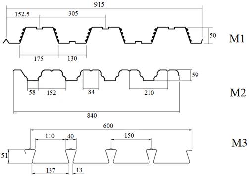
The proposed response variables are the concrete layer thickness, the geometry and thickness of steel deck. The evaluation was made in order to explore the values of one variable while the other two have their fixed values. Effective concrete thickness of 80 mm, 90 mm, 100 mm, 110 mm, 120 mm, 130 mm, 140 mm and 150 mm were evaluated. The geometry of the steel deck consisted of two trapezoidal and one with embossments sections, according to Figure 1, and the studied steel deck thicknesses were 0,80 mm, 0,95 mm and 1,25 mm.
 |
||||
| Figure 1. Steel deck models (in mm). | ||||
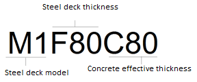
For denomination of the studied models, the order of the nomenclature was chosen as the first letter M followed by the number of the steel deck model, the letter F followed by the steel deck thickness and the letter C followed by the effective concrete thickness in millimeters. The Figure 2 shows an example of the nomenclature utilized in this paper.
 |
||||
| Figure 2. Nomenclature | ||||
As control variables, and for analysis of the slabs of this study, the values of steel and concrete under high temperatures were adopted, as seen in Table 1. The slab model studied is unidirectional and simply supported, forming isostatic elements, with 1-meter of width and 3-meter span. The supports were considered perpendicular to the ribs. There isn’t formation of membrane action compressive strength due to the simply supported model that allows horizontal movements. Also, it was not considered the constructive analysis, as the steel deck must support the total load during the concrete curing period. It was not considered the utilization of negative bending reinforcement in this study, and the positive reinforcement was constituted by the steel deck.
| Table 1. Steel. and concrete properties under high temperatures. | ||||||||||
| Steel properties | Concrete properties | |||||||||
|---|---|---|---|---|---|---|---|---|---|---|
| Characteristic Strength | As Table 1 of NBR 14323 (ABNT, 2013) | As Table 1 of NBR 15200 (ABNT, 2012) | ||||||||
| Poisson’s ratio | 0,3 | 0,15 | ||||||||
| Modulus of elasticity | As Table 1 of NBR 14323 (ABNT, 2013) | As EN 1994-1-2 (EN, 2005) | ||||||||
| Thermal conductivity | As item E.4 of Annex E of NBR 14323 (ABNT, 2013) | As item C.3 of Annex C of NBR 15200 (ABNT, 2012) | ||||||||
| Specific heat | As item E.43 do Annex E of NBR 14323 (ABNT, 2013) | As item C.2 of Annex C of NBR 15200 (ABNT, 2012) | ||||||||
| Specific mass | 7850 kg/m³ | 2500 kg/m³ | ||||||||
The TRFR studied were: 15, 30, 45, 60, 90, 120, 150 and 180 minutes. As NBR 14323 (ABNT 2013) provides the coefficients for steel deck temperature calculation only for TRFR of 60, 90 and 120 minutes, was utilized the software Ansys to obtain the TRFR elements temperature not provided by the standard, calibrating the extrapolations with the values presented by standard.
Ansys utilizes the finite element method in its analysis, with meshing and analyzing their intersection points. This tool was employed to analyze the temperature distribution in the section exposed to a standard fire curve ISO 834 (ISO, 1999). The convection coefficient used was 25 W/m².K. The thermal emissivity of the materials was not considered. Temperature collection was done using Ansys Temperature Probe tool. To measure the steel deck temperature, the exposed faces to fire were selected, adopting as the measurement point the average plane of the respective element that composes the steel deck. In the concrete temperature measurement, the compressed portion of the section was considered.
3. Results
Figure 3, Figure 4 and Figure 5 show the average temperature in the superior face of concrete, above the neutral line.
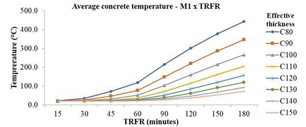
Figure 3.
Average concrete temperature in steel deck model M1
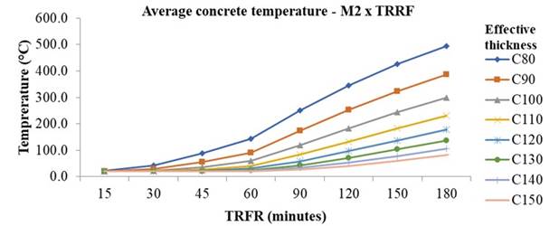
Figure 4.
Average concrete temperature in steel deck model M2
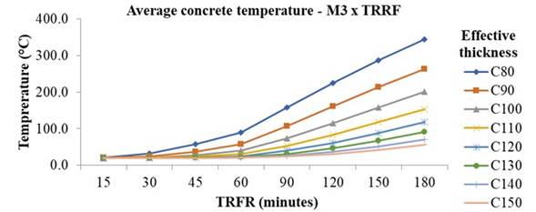
Figure 5.
Average concrete temperature in steel deck model M3.
It is noticed that, only at 60 min of exposure, the temperature variation is larger and more significant in the first four thicknesses, exceeding 100°C and compromising its resistance. At 180 min, only the model M1 with concrete thickness of 14 and 15 cm, the model M2 with concrete thickness of 15 cm and model M3 with concrete thickness of 13 to 15cm do not reach 100ºC. In the other thicknesses, temperatures reached 494.5°C, with a reduction coefficient of 0.61. This behavior of concrete thermal insulation can be explained by its low thermal conductivity and high specific heat, which in the face of fire exposure requires high temperature and duration for heat to be transferred along its thickness. Analyzing the steel deck temperature when verified its geometry under high temperature exposure, the obtained temperatures are similar in the bottom flange and the web, as expected, given the high thermal conductivity of steel.
The Tables 2, 3 and 4 show the resistance reduction factors in the different parts of the steel deck.
The geometry of the M3 model has the largest temperature variation in the elements, showing the smallest temperatures on the top flange and the highest in the bottom flange and web amount the studied models. As consequence, this model has the biggest reduction factor in the top flange and the smallest in the bottom flange and web. This variation is within a range of 133°C and is influenced by the area and form of exposure, which, because of the re-entrant model, ends up isolating the top flange and leaving a larger exposure area on the bottom flange, which is transferred to the web.
Table 2. Top flange resistance reduction factors
Model
15 min
30 min
45 min
60 min
90 min
120 min
150 min
180 min
M1
1,00
0,72
0,42
0,25
0,12
0,08
0,06
0,05
M2
1,00
0,79
0,47
0,30
0,15
0,09
0,08
0,07
M3
1,00
0,89
0,64
0,43
0,22
0,13
0,10
0,09
Table 3. Bottom flange resistance reduction factors
Model
15 min
30 min
45 min
60 min
90 min
120 min
150 min
180 min
M1
1,00
0,65
0,34
0,20
0,09
0,06
0,05
0,04
M2
1,00
0,61
0,28
0,16
0,08
0,05
0,05
0,05
M3
1,00
0,52
0,24
0,14
0,07
0,05
0,05
0,04
Table 4. Web resistance reduction factors
Model
15 min
30 min
45 min
60 min
90 min
120 min
150 min
180 min
M1
1,00
0,65
0,34
0,20
0,09
0,06
0,05
0,04
M2
1,00
0,61
0,28
0,16
0,08
0,05
0,05
0,05
M3
1,00
0,52
0,24
0,14
0,07
0,05
0,05
0,04
The steel deck temperature did not suffer a significative variation with the change of thickness, due to the high thermal conductivity of steel and reduced dimensions of steel deck. In NBR 14323 (ABNT, 2013) calculation model, only the steel deck geometry influences de temperature variation and it is the same for all thicknesses of the same model. This procedure was confirmed by Ansys verification, as the variation did not exceed 1% amount of the thicknesses.
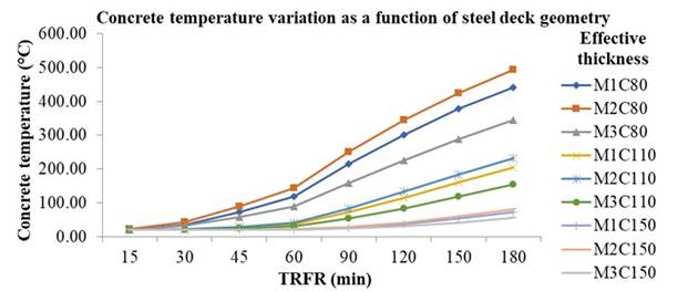
Correlating the variables that influence the slab strength at high temperatures (steel deck geometry and concrete layer thickness) and averaging these values with the steel deck thickness, it can be stated that the differences in temperature as a function of geometry are more significant in the smaller concrete thicknesses, decreasing as thickness increases as shown in Figure 6. Despite this, the advantage of the M3 model over the other models has always been observed. As the TRFR increased, the temperature difference relative to the thickness of the concrete layer decreased.
 |
||||
| Figure 6. Concrete temperature variation as a function of steel deck geometry | ||||
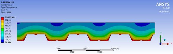
The model M1 presents a similar geometry to model M2, as shown in Figures 7 and 8, which makes the temperature variation between these two models smaller. The most significative variation is between the models M2 and M3 geometry, the first has the highest temperature and the second the lowest temperature among the models studied. This is because the M2 model geometry exposes more to its top flange, making it easier for the temperature to reach higher values in the concrete. The model M3 is re-entrant, which allows the heat to concentrate in the bottom flange and difficult the access of hot air in the top flange, as shown in Figure 9. The isotherms also show how the temperature advances in the slabs, and in the M3 model they behave steadily, forming straight lines, while in the other two models they form waves.
 |
||||
| Figure 7. M1F80C110 with TRRF of 180 minutes | ||||
The variable that most influenced the temperature was the steel deck geometry, specifically the M3 model with re-entrant, having the best performance among the studied models. This was due to the larger unitary steel area of these elements and higher concrete consumption - with higher thermal stability - in the ribs.
The effective concrete layer thickness was also influent. Because the concrete has low thermal conductivity, the higher its thickness, the lower the temperature of the slab compressive strength, where the concrete effectively acts at the resistant moment. The drawback of this solution is the increased weight of the structure.
From 30 minutes of exposure to fire, the reduction coefficient of the steel deck shows that it has no more structural participation, leaving the concrete with no reinforcement, subjected to bending. Therefore, in numerical analyzes designed based on normative equations, the use of positive reinforcement is necessary to avoid sudden breaking of concrete at high temperatures. However, experimental studies have shown that these slabs have an intrinsic fire resistance, having seen the membrane effect that is difficult to predict numerically.
4. Conclusion
Among the items evaluated in this work, the ones that exert the greatest influence on the behavior of composite concrete and steel slabs are the steel deck geometry and the concrete layer thickness, respectively. This is mainly due to the thermal stability generated by the geometry that allows higher concrete consumption and the low thermal conductivity of the concrete.
References
Associação Brasileira de Normas Técnicas (2013). NBR 14323: Projeto de estruturas de aço e de estruturas mistas de aço e concreto de edifícios em situação de incêndio. Rio de Janeiro.
Associação Brasileira de Normas Técnicas (2008). NBR 8800: Projeto de Estruturas De Aço e de estruturas mistas de aço e concreto de edifícios. Rio de Janeiro.
Associação Brasileira de Normas Técnicas (2010). NBR 14762: Dimensionamento de estruturas de aço constituídas por perfis formados a frio. Rio de Janeiro.
Associação Brasileira de Normas Técnicas (2012). NBR 15200: Projeto de estruturas de concreto em situação de incêndio. Rio de Janeiro.
Bailey, C. G.; White, D. S.; Moore, D. B. (2000). The tensile membrane action of unrestrained composite slabs simulated under fire conditions. Engineering Structures. 22 (12):1583-1595. https://doi.org/10.1016/S0141-0296(99)00110-8
Costa, C. N.; Figueiredo, A. D.; Pignatta, V. (2002). O fenômeno do lascamento (“spalling”) nas estruturas de concreto armado submetidas a incêndio - uma revisão crítica. In: In: 44º Congresso Brasileiro do Concreto- IBRACON 2002. Anais eletrônicos. Belo Horizonte.
Craveiro, H. D. S. (2010). “Análise do comportamento estrutural de lajes mistas aço-betão com reforço transversal”. Dissertação de mestrado. Universidade de Coimbra, Coimbra.
European Committee for Standardization (2005). EN 1994-1-2: Design of composite steel and concrete structures - Part 1-2: General rules - structural fire design: Eurocode 4. Brussels.
Gillie, M.; Usmani, A. S.; Rotter, J. M. (2001). A structural analysis of the first Cardington test. Journal of Constructional Steel Research. 57 (6):581-601. https://doi.org/10.1016/S0143-974X(01)00004-9
Li, G.; Zhang, N.; Jiang, J. (2017). Experimental investigation on thermal and mechanical behaviour of composite floors exposed to standard fire. Fire Safety Journal. 89:63-76. https://doi.org/10.1016/j.firesaf.2017.02.009
Liang, Q. Q. (2015). “Analysis and Design of Steel and Composite Structures”. CRC Press, New York. p. 458. ISBN: 9780415532204
Li, G.; Wang, P. (2013). “Advanced Analysis and Design for Fire Safety of Steel Structures”. China: Zhejiang University Press, Springer-Verlag Berlin Heidelberg. p. 357. ISBN: 9783642343933
Nguyen, T. T.; Tan, K. H.; Burgess, I. W. (2015). Behaviour of composite slab-beam systems at elevated temperatures: Experimental and numerical investigation. Engineering Structures, 82: 199-213. https://doi.org/10.1016/j.engstruct.2014.10.044
Omer, E.; Izzuddin, B. A.; Elghazouli, A. Y. (2009). Failure of lightly reinforced concrete floor slabs with planar edge restraints under fire. Journal of Structural Engineering, 135 (9): 1068-1080. https://doi.org/10.1061/(ASCE)0733-9445(2009)135:9(1068)
Selamet, S.; Bolukbas, C. (2016). Fire resilience of shear connections in a composite floor: Numerical investigation. Fire Safety Journal, 81: 97-108. https://doi.org/10.1016/j.firesaf.2016.02.003
Vargas, M. R.; Silva, V. P. (2005). Resistência ao fogo das estruturas de aço. Rio de Janeiro: IBS/CBCA. Rio de Janeiro. P.78. ISBN: 85-89819-02-7.
Wang, Y. C. (Ed.). (2002). “Steel and Composite Structures:Behaviour and Design for Fire Safety”. 1 ed. London: CRC Press. p. 352. ISBN: 9780429257056. DOI: https://doi.org/10.1201/9781482267693
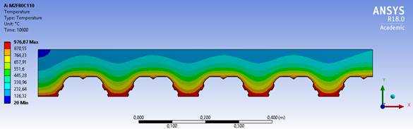
Figure 8.
M2F80C110 with TRRF of 180 minutes
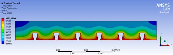
Figure 9.
M3F80C110 with TRRF of 180 minutes