
| Basic Research | https://doi.org/10.21041/ra.v10i3.432 |
An analytical model for the design of corner combined footings
Um modelo analítico para projeto de sapata de canto combinadas
Un modelo analítico para el diseño de zapatas combinadas de esquina
A. Luévanos
Rojas1
*
![]() , S. López Chavarría1
, S. López Chavarría1
![]() , M. Medina Elizondo1
, M. Medina Elizondo1
![]() , R. Sandoval Rivas1
, R. Sandoval Rivas1
![]() , O. M. Farías Montemayor1
, O. M. Farías Montemayor1
![]()
1 Instituto de Investigaciones Multidisciplinarias, Universidad Autónoma de Coahuila, Torreón, Coahuila, México. .
*Contact author: arnulfol_2007@hotmail.com
Reception: August 24, 2019.
Acceptance: April 06, 2020.
Publication: September 01, 2020
| Cite as: Luévanos Rojas, A., López Chavarría, S., Medina Elizondo, M., Sandoval Rivas, R., Farías Montemayor, O. M. (2020), "An analytical model for the design of corner combined footings", Revista ALCONPAT, 10 (3), pp. 317 – 335, DOI: https://doi.org/10.21041/ra.v10i3.432 |
Abstract
This work shows an analytical model for the design of corner combined footings subjected to an axial load and two orthogonal flexural moments per each column. It considers the real pressure on the ground below of the footing, and the methodology is based on the principle that the integration of the shear force is the moment. The current design considers the maximum pressure at all contact points. This model is verified by equilibrium of shear forces and moments. The application of the model is presented by means of a numerical example. Therefore, the proposed model is the most appropriated, because it generates better quality control in the resources used.
Keywords:
corner combined footings,
analytical model for design,
flexural moments,
flexural shearing,
punching shearing.
Resumo
Este trabalho apresenta um modelo analítico para o dimensionamento de sapatas angulares combinadas submetidas a uma carga axial e dois momentos fletores ortogonais para cada pilar que leva em consideração a pressão real do solo sob a sapata, e a metodologia é baseada no princípio de que a integração da força cortante é o momento. O projeto atual considera a pressão máxima em todos os pontos de contato. Este modelo é verificado pelo equilíbrio das forças de cisalhamento e momentos. A aplicação do modelo é apresentada por meio de um exemplo numérico. Portanto, o modelo proposto é o mais adequado, pois gera um melhor controle de qualidade dos recursos utilizados.
Palavras-chave:
sapatas combinadas de canto,
modelo analítico para projeto,
momentos de flexão,
cisalhamento por flexão,
cisalhamento por punção.
Resumen
Este trabajo muestra un modelo analítico para el diseño de zapatas combinadas de esquina sometidas a una carga axial y dos momentos flexionantes ortogonales por cada columna. El modelo toma en cuenta la presión real del suelo debajo de la zapata, y la metodología se basa en el principio de que la integración de la fuerza de corte es el momento. El diseño actual considera la presión máxima en todos los puntos de contacto. Este modelo se verifica por equilibrio de fuerzas de corte y momentos. La aplicación del modelo se presenta por medio de un ejemplo numérico. Por lo tanto, el modelo propuesto es el más apropiado, ya que genera un mejor control de calidad en los recursos utilizados.
Palabras clave:
zapatas combinadas de esquina,
modelo analítico para diseño,
momentos flexionantes,
cortante por flexión,
cortante por penetración.
1. Introduction
A foundation or more commonly called a base that is the element of an architectural structure that connects it to the ground, and that transfers the loads from the structure to the ground. Foundations are divided into two types, such as shallow and deep (Bowles, 2001; Das et al., 2006).
Five main types of shallow foundations for columns are: 1) strip footing; 2) spread or isolated footing; 3) combined footing supporting two or more columns; 4) strap or cantilever footing; 5) raft or mat foundations covering the whole foundation area (Bowles, 2001).
A combined footing is necessary to support a column located very close to the edge of a property line so as not to invade the adjacent property. The combined footing can be a uniform thickness slab or an inverted T-beam. If the slab type of the combined footing is used to support two or more columns (typically two), the slab must have a rectangular, trapezoidal or T-shaped form when one column is loaded more than the other (Kurian, 2005; Punmia et al., 2007; Varghese, 2009).
The ground pressure under a footing depends on the type of ground, the relative rigidity of the ground and the footing, and the depth of foundation at level of contact between footing and ground.
Figure 1 shows the distribution of ground pressure under the footing according to the type of ground and the stiffness of the footing (Bowles, 2001).
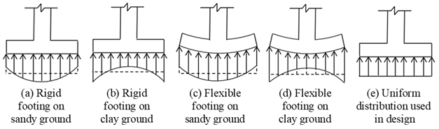
Figure 1. Soil pressure below of the footing
Studies on foundation structures and mathematical models for footings have been successfully investigated in various geotechnical engineering problems. The main contributions of various researchers in the last decade are: “Behavior of repeatedly loaded rectangular footings resting on reinforced sand” (El Sawwaf and Nazir, 2010); “Nonlinear vibration of hybrid composite plates on elastic foundations” (Chen et al., 2011); “Stochastic design charts for bearing capacity of strip footings” (Shahin and Cheung, 2011); “Modified particle swarm optimization for optimum design of spread footing and retaining wall” (Khajehzadeh et al., 2011); “Design of isolated footings of rectangular form using a new model” (Luévanos-Rojas et al., 2013); “Design of isolated footings of circular form using a new model” (Luévanos-Rojas, 2014a); “Design of boundary combined footings of rectangular shape using a new model” (Luévanos-Rojas, 2014b); “Determination of the ultimate limit states of shallow foundations using gene expression programming (GEP) approach” (Tahmasebi poor et al., 2015); “Design of boundary combined footings of trapezoidal form using a new model” (Luévanos-Rojas, 2015); “New iterative method to calculate base stress of footings under biaxial bending” (Aydogdu, 2016); “A comparative study for the design of rectangular and circular isolated footings using new models” (Luévanos-Rojas, 2016a); “Influence of footings stiffness on punching resistance” (Fillo et al., 2016); “A new model for the design of rectangular combined boundary footings with two restricted opposite sides” (Luévanos-Rojas, 2016b); “Structural design of isolated column footings” (Abdrabbo et al., 2016); “Optimal design for rectangular isolated footings using the real pressure on the ground” (Luévanos-Rojas et al., 2017a); “Experimental and finite element analyses of footings of varying shapes on sand” (Anil et al., 2017); “A comparative study for design of boundary combined footings of trapezoidal and rectangular forms using new models” (Luévanos-Rojas et al., 2017b); “Performance of isolated and folded footings” (El-kady and Badrawi, 2017); “Analysis and Design of Various Types of Isolated Footings” (Balachandar and Narendra Prasad, 2017); “A new model for T-shaped combined footings Part II: Mathematical model for design” (Luévanos-Rojas et al., 2018); “Punching shear resistance of reinforced concrete footings: evaluation of design codes” (Santos et al., 2018); “Soil foundation effect on the vibration response of concrete foundations using mathematical model” (Dezhkam and Yaghfoori, 2018); “Nonlinearity analysis in studying shallow grid foundation” (Ibrahim et al., 2018); “Modeling for the strap combined footings Part II: Mathematical model for design” (Yáñez-Palafox et al., 2019); “Numerical method for analysis and design of isolated square footing under concentric loading” (Magade and Ingle, 2019).
The document related to this work is: “Optimal dimensioning for the corner combined footings” to obtain only the minimum area of the contact surface between the ground and the footing (López-Chavarría et al., 2017), but this document does not present the design of corner combined footings to obtain the effective depth (effective cant) and reinforcing steel.
This document shows an analytical model for the design of corner combined footings subjected to an axial load and two orthogonal flexural moments for each column, and the ground pressure on the footing is presented in terms of the effects generated by each column, and the methodology is based on the principle that the integration of the shear force is the moment. The current design considers the maximum pressure at all contact points, because the center of gravity of the footing coincides with the position of the force resulting from the loads. This model is verified by equilibrium of shear forces and moments. The main advantage of the proposed model is to present the moment, the flexural shearing and the punching shearing by mean of analytical equations. Therefore, the proposed model will be the most appropriate, since it generates a better quality control in the resources used (labor, materials, minor equipment, etc.), because it adjusts to the conditions of the real pressure on the ground.
2. Formulation of the proposed model
The critical sections for footings according to the code are (ACI 318S-14, 2014): 1) The moment is located on the face of the column; 2) The flexural shearing is located at a distance “d” from the face of the column; 3) The punching shearing is presented at a distance of “d/2” in both directions.
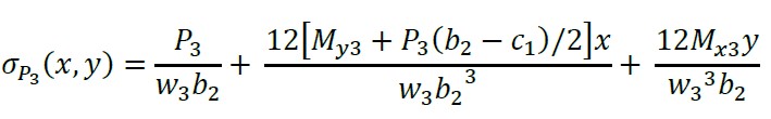
The axial load and two orthogonal flexural moments (biaxial flexure) of each column applied to the corner combined footing are shown in Figure 2(a). The pressure below of the corner combined footing that varies linearly, and stress at each vertex of the footing is presented in Figure 2(b).
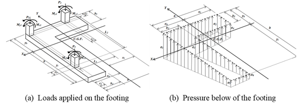
Figure 2.
Corner combined footing
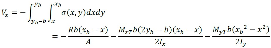
The stresses in the main direction (“X” and “Y” axes) are:
(1)
where: R, M xT , M yT , A, I x , and I y are shown in (López-Chavarría et al., 2017).
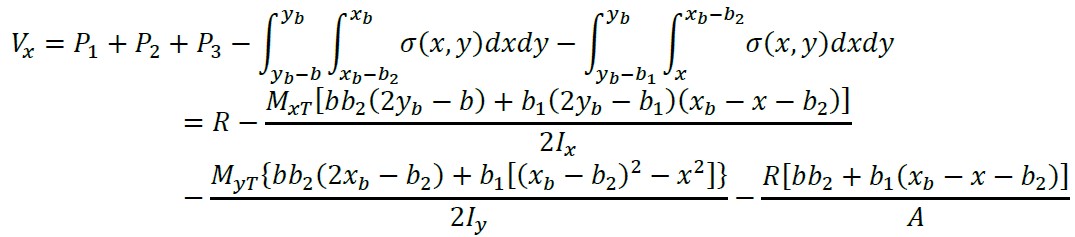
The stresses below of the column 2 (“X 2” and “Y 2” axes) are (see Figure 3):
(2)
The stresses below of the column 3 (“X 3” and “Y 3” axes) are (see Figure 3):
(3)
where: w 2 and w 3 are the widths of the analysis surface in the columns 2 and 3: w 2 = c 2 + d, w 3 = c 4 + d.
2.1 Flexural shearing and flexural moments
The critical sections for flexural moments are presented on the axes: a’-a’, b’-b’, c’-c’, d’-d’, e’-e’, f’-f’, g’-g’, h’-h’, i’-i’ and j’-j’ (see Figure 3). The critical sections for flexural shearing are presented on the axes: k’-k’, l’-l’, m’-m’, n’-n’, o’-o’, p’-p’, q’-q’ and r’-r’ (see Figure 4).
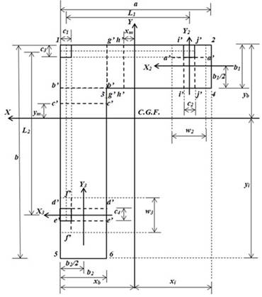
Figure 3.
Critical sections for flexural moments
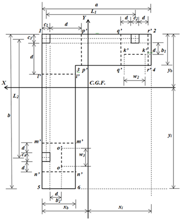
Figure 4.
Critical sections for flexural shearing
Note: When the moments around the X axis are obtained, the moments around the Y axis are considered equal to zero. When the moments around the Y axis are obtained, the moments around the X axis do not influence. Because these are perpendicular axes between them.
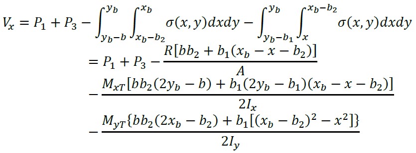
2.1.1 Flexural shearing and moments on an axis parallel to the “X2” axis of - b1/2 ≤ y2 ≤ b1/2 - c 3 /2
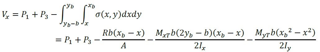
Shear force “V y2 ” is found through the pressure volume of the area formed by the “X 2” axis with a width “w 2 = c 2 + d” and the free end (inner side) of the footing:
(4)
The moment by integration of equation (4) with respect to “y 2” is:

(5)
where: M X2 is the moment around the “X 2” axis, and V y2 is the shear force at a distance “y 2”.
Now, substituting “y 2 = − b 1/2” and “M X2 = 0” into equation (5), we obtain the constant “C 1”:
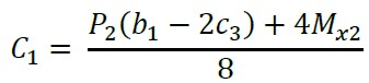
(6)
Substituting equation (6) into equation (5) and the generalized moment equation is presented as follows:
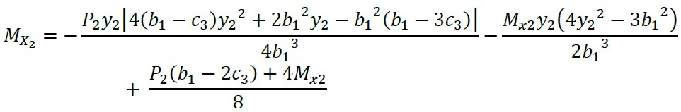
(7)
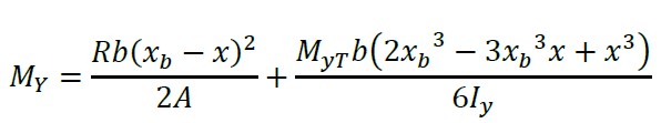
2.1.2 Flexural shearing and moments on an axis parallel to the “X” axis of yb - c3/2 ≤ y ≤ yb
Shear force “V y ” is found through the pressure volume of the area formed by the “X” axis with a width “a” and the free end (top side) of the footing:
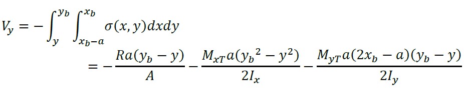
(8)
The moment by integration of equation (8) with respect to “y” is:
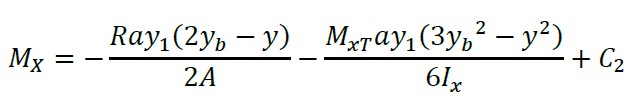
(9)
where: M X is the moment around the “X” axis, and V y is the shear force at a distance “y”.
Now, substituting “y = y b ” and “M X = 0” into equation (9), we obtain the constant “C 2”:
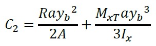
(10)
Substituting equation (10) into equation (9) and the generalized moment equation is presented as follows:
(11)
Substituting “y = y b − c 3/2” into equation (11), we obtain the moment around the axis located in the center of column 1 and 2 “M c3/2 ”:
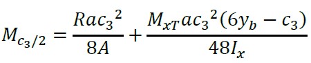
(12)
2.1.3 Flexural shearing and moments on an axis parallel to the “X” axis of yb - b1 ≤ y ≤ yb - c3/2
Shear force “V y ” is found through the pressure volume of the area formed by the “X” axis with a width “a” and the top side of the footing:
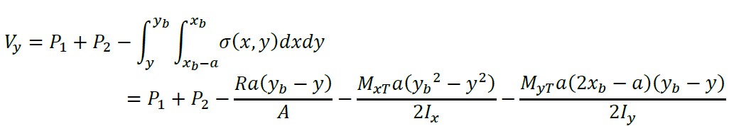
(13)
The moment by integration of equation (13) with respect to “y” is:
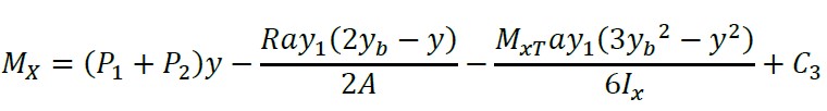
(14)
Now, substituting “y = y b - c 3/2” and “M X = M c3/2 - M x1 - M x2 ” into equation (14), we obtain the constant “C 3”:
(15)
Substituting equation (15) into equation (14) and the generalized moment equation is presented as follows:

(16)
Substituting “y = y b - b 1” into equation (16), we obtain the moment around the b’-b’ axis “M b1 ”:

(17)
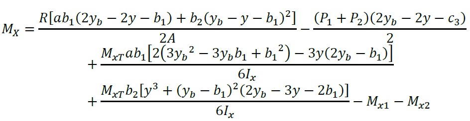
2.1.4 Flexural shearing and moments on an axis parallel to the “X” axis of yb - L2 - c3/2 ≤ y ≤ yb - b1
Shear force “V y ” is found through the pressure volume of the area formed by the “X” axis and the top side of the footing:
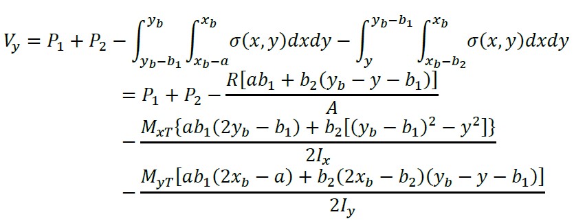
(18)
The moment by integration of equation (18) with respect to “y” is:
(19)
Now, substituting “y = y b - b 1” and “M X = M b1 ” into equation (19), we obtain the constant “C 4”:
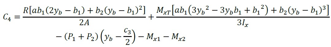
(20)
Substituting equation (20) into equation (19) and the generalized moment equation is presented as follows:
(21)
Substituting “y = y b - L 2 - c 3/2” into equation (21), we obtain the moment around the axis located in the center of column 3 “M L2 ”:
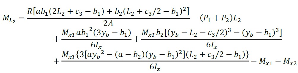
(22)
2.1.5 Flexural shearing and moments on an axis parallel to the “X” axis of yb - b ≤ y ≤ yb - L2 - c 3 /2
Shear force “V y ” is found through the pressure volume of the area formed by the “X” axis and the top side of the footing:
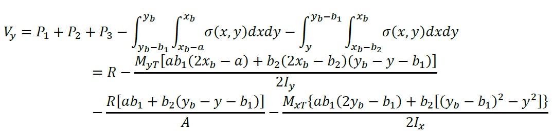
(23)
The moment by integration of equation (23) with respect to “y” is:
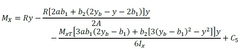
(24)
Now, substituting “y = y b - L 2 - c 3/2” and “M X = M L2 - M x3 ” into equation (24), we obtain the constant “C 5”:
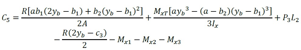
(25)
Substituting equation (25) into equation (24) and the generalized moment equation is presented as follows:
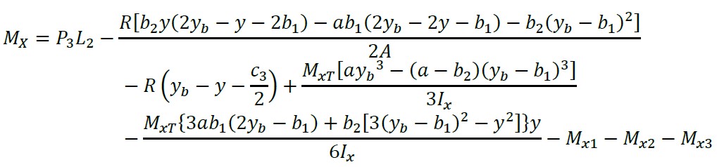
(26)
In the next paragraphs we get the equations of the shear forces and generalized moments by the procedure used above. Therefore, the equations for shear forces and generalized moments are shown below.
2.1.6 Flexural shearing and moments on an axis parallel to the “Y3” axis of - b2/2 ≤ x3 ≤ b2/2 - c1/2
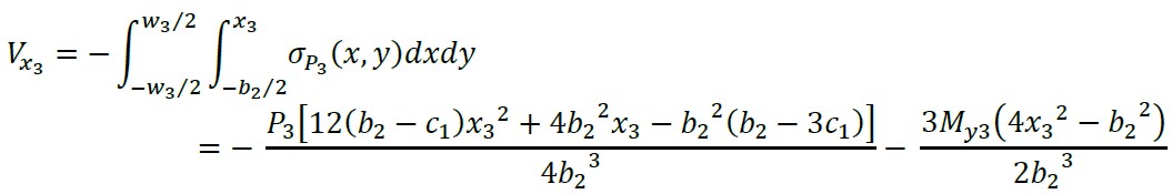
(27)
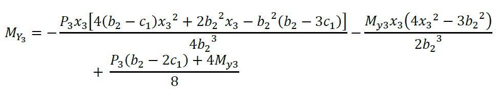
(28)
2.1.7 Flexural shearing and moments on an axis parallel to the “Y” axis of xb - c1/2 ≤ x ≤ xb
(29)
(30)
2.1.8 Flexural shearing and moments on an axis parallel to the “Y” axis of xb - b2 ≤ x ≤ xb - c1/2
(31)

(32)
2.1.9 Flexural shearing and moments on an axis parallel to the “Y” axis of xb - L1 - c1/2 ≤ x ≤ xb - b2
(33)
(34)
2.1.10 Flexural shearing and moments on an axis parallel to the “Y” axis of xb - a ≤ x ≤ xb - L1 - c 1 /2
(35)
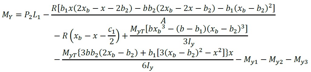
(36)
2.2 Punching shearing
The critical sections for punching shearing are shown in Figure 5.
2.2.1 Punching shearing for the corner column (column 1)
The critical section for column 1 is presented at the perimeter formed by points 1, 7, 8 and 9 of the footing (see Figure 5). The punching shearing is obtained by the axial load of column 1 minus the pressure volume of the area delimited by points 1, 7, 8 and 9:
(37)
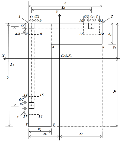
Figure 5.
Critical sections for punching shearing
2.2.2 Punching shearing for the column of a limit (column 2)
The critical section for column 2 is presented at the perimeter formed by points 10, 11, 12 and 13 of the footing (see Figure 5). The punching shearing is obtained by the axial load of column 2 minus the pressure volume of the area delimited by points 10, 11, 12 and 13:
(38)
Note: when d/2 ≤ a - L 1 - (c 1 + c 2)/2 → t = d/2, and when d/2 > a - L 1 - (c 1 + c 2)/2 → t = a - L 1 - (c 1 + c 2)/2.
2.2.3 Punching shearing for the column of a limit (column 3)
The critical section for column 3 is presented at the perimeter formed by points 14, 15, 16 and 17 of the footing (see Figure 5). The punching shearing is obtained by the axial load of column 3 minus the pressure volume of the area delimited by points 14, 15, 16 and 17:
(39)
Note: when d/2 ≤ b - L 2 - (c 3 + c 4)/2 → s = d/2, and when d/2 > b - L 2 - (c 3 + c 4)/2 → t = b - L 2 - (c 3 + c 4)/2.
3. Verification of the proposed model
The model proposed in this document is verified as follows:
1.- For flexural moments on the X2 and X axes: When “y 2 = − b 1/2” is substituted into equation (7) we obtain M X2 = 0, if “y = y b” is substituted into equation (11) we obtain M X = 0, and substituting “y = y b − b” into equation (26) we obtain M X = 0. Therefore, the equations for the moments on the X2 and X axes satisfy the equilibrium.
2.- For flexural moments on the Y3 and Y axes: When “x 3 = − b 2/2” is substituted into equation (28) we obtain M Y3 = 0, if “x = x b” is substituted into equation (30) we obtain M Y = 0, and substituting “x = x b − a” into equation (36) we obtain M Y = 0. Therefore, the equations for the moments on the Y3 and Y axes satisfy the equilibrium.
3.- For flexural shearing on the X2 and X axes: When “y 2 = − b 1/2” is substituted into equation (4) we obtain V y2 = 0, if “y = y b” is substituted into equation (8) we obtain V y = 0, and substituting “y = y b − b” into equation (23) we obtain V y = 0. Therefore, the equations for the flexural shearing on the X2 and X axes satisfy the equilibrium.
4.- For flexural shearing on the Y3 and Y axes: When “x 3 = − b 2/2” is substituted into equation (27) we obtain V x3 = 0, if “x = x b” is substituted into equation (29) we obtain V x = 0, and substituting “x = x b − a” into equation (35) we obtain V x = 0. Therefore, the equations for the flexural shearing on the Y3 and Y axes satisfy the equilibrium.
4. Application of the proposed model
The design of a corner combined footing that supports three square columns is shown below with the following information: the three columns are of 40x40 cm, L 1 = 5.00 m, L 2 = 5.00 m, H (depth of the footing) = 2.0 m, P D1 = 300 kN, P L1 = 200 kN, M Dx1 = 80 kN-m, M Lx1 = 70 kN-m, M Dy1 = 120 kN-m, M Ly1 = 80 kN-m, P D2 = 600 kN, P L2 = 400 kN, M Dx2 = 160 kN-m, M Lx2 = 140 kN-m, M Dy2 = 120 kN-m, M Ly2 = 80 kN-m, P D3 = 500 kN, P L3 = 400 kN, M Dx3 = 120 kN-m, M Lx3 = 80 kN-m, M Dy3 = 150 kN-m, M Ly3 = 100 kN-m, f’ c = 28 MPa, f y = 420 MPa, q a = 252 kN/m 2 , γ c (concrete density) = 24 kN/m 3 , γ s (ground fill density) = 15 kN/m 3 .
The loads and moments acting on the corner combined footing are: P 1 = 500 kN-m, M x1 = 150 kN-m, M y1 = 200 kN-m, P 2 = 1000 kN, M x2 = 300 kN-m, M y2 = 200 kN-m, P 3 = 900 kN, M x3 = 200 kN-m, M y3 = 250 kN-m.
The available load capacity of the ground is assumed of σ máx = 213.00 kN/m 2, because at the load capacity of the ground “q a ” is subtracted from the weight of the footing (γ c by the thickness of the footing), and the weight of the filling of the ground (γ s by the thickness of the filling).
Substituting σ máx , L 1 , L 2 , P 1 , M x1 , M y1 , P 2 , M x2 , M y2 , P 3 , M x3 , M y3 into equations (30) to (42) from work (López-Chavarría et al. 2017), and the solution by MAPLE-15 software is: A min = 11.31 m 2 , M xT = − 8.65 kN-m, M yT = 9.49 kN-m, R = 2400 kN, a = 6.36 m, b = 5.95 m, b 1 = 1.00 m, b 2 = 1.00 m, σ 1 = 211.31 kN/m 2 , σ 2 = 212.75 kN/m 2 , σ 3 = 211.78 kN/m 2 , σ 4 = 213.00 kN/m 2 , σ 5 = 212.77 kN/m 2 , σ 6 = 213.00 kN/m 2 .
The practical dimensions of the corner combined footing that supports three square columns are: a = 6.40 m, b = 6.00 m, b 1 = 1.00 m, b 2 = 1.00 m. Now, the practical dimensions to verify the stresses are substituted in the same software MAPLE-15, and the solution is: A min = 11.40 m 2 , M xT = 27.89 kN-m, M yT = 7.89 kN-m, R = 2400 kN, a = 6.40 m, b = 6.00 m, b 1 = 1.00 m, b 2 = 1.00 m, σ 1 = 212.30 kN/m 2 , σ 2 = 211.11 kN/m 2 , σ 3 = 211.34 kN/m 2 , σ 4 = 210.34 kN/m 2 , σ 5 = 207.68 kN/m 2 , σ 6 = 207.49 kN/m 2 .
The geometric properties of the footing are: x b = 2.02 m, y b = 1.82 m, I x = 36.21 m 4, I y = 42.73 m 4.
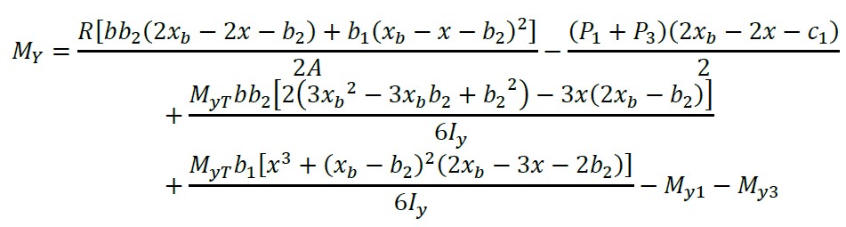
The factorized loads and moments acting on the footing are: P u1 = 680 kN, M ux1 = 208 kN-m, M uy1 = 272 kN-m, P u2 = 1360 kN, M ux2 = 416 kN-m, M uy2 = 272 kN-m, P u3 = 1240 kN, M ux3 = 272 kN-m, M uy3 = 340 kN-m. The resulting loads and moments factorized by equations (31) to (33) (López-Chavarría et al., 2017) are obtained: R u = 3280 kN, M uxT = − 4.21 kN-m, M uyT = 39.79 kN-m.
The moment on the a’-a’ axis by equation (7) is obtained “M a’ = 289.15 kN-m” in y 2 = b 1/2 - c 3. The moment on the b’-b’ axis by equation (16) is obtained “M b’ = − 1335.85 kN-m” in y = y b - b 1. Now, substituting the corresponding values into equation (21) and deriving with respect to “y”, this is equal to zero to obtain the position the maximum moment “y m = 0.12 m”, subsequently, it is substituted in equation (21), and the moment is obtained “M c’ = − 1405.08 kN-m”. The moment on the d’-d’ axis by equation (21) is obtained “M d’ = 168.08 kN-m” in y = y b - L 2 - c 3/2 + c 4/2. The moment on the e’-e’ axis by equation (26) is obtained “M e’ = 51.87 kN-m” in y = y b - L 2 - c 3/2 - c 4/2.
The moment on the f’-f’ axis by equation (28) is obtained “Mf’ = 238.18 kN-m” in x3 = b2/2 - c1. The moment on the g’-g’ axis by equation (32) is obtained “Mg’ = − 1280.14 kN-m” in x = xb - b2. Now, substituting the corresponding values into equation (34) and deriving with respect to “x”, this is equal to zero to obtain the position the maximum moment “xm = 0.37 m”, subsequently, it is substituted in equation (34), and the moment is obtained “Mh’ = − 1339.60 kN-m”. The moment on the i’-i’ axis by equation (34) is obtained “M i’ = 278.39 kN-m” in x = x b - L 1 - c 1/2 + c 2/2. The moment on the j’-j’ axis by equation (36) is obtained “M j’ = 141.97 kN-m” in x = x b - L 1 - c 1/2 - c 2/2.
The effective cant below column 2 is: 18.33 cm. The effective cant for the maximum moment “M c’ ” is: 46.42 cm. The effective cant below column 3 is: 16.63 cm. The effective cant for the maximum moment “Mh’ ” is: 45.32 cm. The effective cant after several proposals is: d = 92.00 cm, r = 8.00 cm and t = 100 cm.
Table 1 shows the flexural shearing acting on the footing and those resisted by the concrete according to the code (ACI 318S-14).
Table 1. Flexural shearing.
Axes
Coordinates
Analysis width cm
Flexural shearing
Acting kN
Resisted kN
k'
y2 = b1/2 – c3 – d
132
0*
928.56
l'
y = yb – c3 – d
100
114.14
703.45
m'
y = yb – c3/2 – L2 + c4/2 + d
100
– 684.15
703.45
n'
y = yb – c3/2 – L2 – c4/2 – d
100
0*
703.45
o'
x3 = b2/2 – c1 – d
132
0*
928.56
p'
x = xb – c1 – d
100
92.11
703.45
q'
x = xb – c1/2 – L1 + c2/2 + d
100
– 699.81
703.45
r'
y = yb – c3/2 – L2 – c4/2 – d
100
22.68
703.45
* The axis is located outside the footing area.
Table 2 shows the punching shearing acting on the footing and those resisted by the concrete according to the code (ACI 318S-14).
Table 2. Punching shearing.
Column
Critical perimeter
Punching shearing
Acting kN
Resisted kN
1
b0 = c1 + c3 + d
466.23
3629.81
7500.95
2348.70
2
b0 = c2 + 2c3 + 2d
1036.93
6415.49
13112.93
4151.20
3
b0 = 2c1 + c4 + 2d
911.26
6415.49
13112.93
4151.20
Table 3 shows the reinforcing steel of the corner combined footing (ACI 318S-14).
Table 3. Reinforcing steel of the footing.
Reinforcing steel
Area cm2
Direction of the "Y" axis
Steel on the top with a width b2
Main steel
42.10
Minimum steel
30.67
Steel proposed
45.63 (9Ø1")
Steel on the top with a width a − b2
Steel by temperature
97.20
Steel proposed
99.75 (35Ø3/4")
Steel at the bottom with a width b2
Main steel
4.86
Minimum steel
30.67
Steel proposed
35.49 (7Ø1")
Steel below of the column 2 with a width w2
Main steel
8.37
Minimum steel
40.48
Steel proposed
42.75 (15Ø3/4")
Steel at the bottom with a width a − b2 − w2
Steel by temperature
73.44
Steel proposed
74.10 (26Ø3/4")
Direction of the "X" axis
Steel on the top with a width b1
Main steel
40.06
Minimum steel
30.67
Steel proposed
40.56 (8Ø1")
Steel on the top with a width b – b1
Steel by temperature
90.00
Steel proposed
91.20 (32Ø3/4")
Steel at the bottom with a width b1
Main steel
8.07
Minimum steel
30.67
Steel proposed
35.49 (7Ø1")
Steel below of the column 3 with a width w3
Main steel
6.88
Minimum steel
40.48
Steel proposed
42.75 (15Ø3/4")
Steel at the bottom with a width b – b1 – w3
Steel by temperature
66.24
Steel proposed
68.40 (24Ø3/4")
The effects that govern the thickness of the footings are the moments, the flexural shearing and the punching shearing, and the reinforcing steel is designed by the moments. For the thickness of the numerical example, it governs by the flexural shearing on the q’-q’ axis (see Table 1).
Table 4 shows the minimum development length for deformed bars “l d ” and the available length “l a ”.
Thus, the available length is greater than the minimum development length in both directions (top and bottom) (see Table 4). Therefore, the hooks are not necessary for the corner combined footing.
Table 4. Minimum development length and available length.
Location of steel
ψt
ψe = λ
Development length cm
Available length
Direction of the "X" axis cm
Direction of the "Y" axis cm
Top
1.3
1.0
154.17
165
170
Bottom
1.0
1.0
96.00
140
100
Figure 6 shows in detail the reinforcing steel and the dimensions of the corner combined footing.
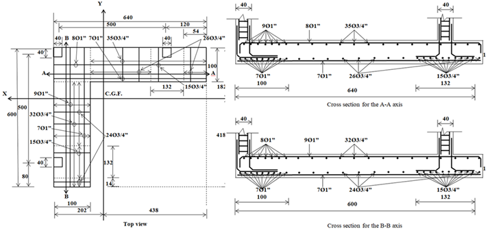
Figure 6.
Final design of the corner combined footing
5. Conclusions
The new model presented in this work is applied only for the design of corner combined footings. The assumptions are: the structural member is rigid and the ground that supports the footing is elastic and homogeneous, which complies with the expression of the biaxial flexure, i.e., the pressure varies linearly.
The new model presented in this document concludes the following:
1.- The thickness for the corner combined footings is governed by the flexural shearing, and the isolated footings are governed by the punching shearing.
2.- The new model is not limited, whereas the current design assumes that the maximum pressure at all contact points, i.e., the force resulting from the applied loads coincides with the position of the geometric center of the footing.
3.- The new model is more suited to real conditions with respect to the current design, because the new model takes into account the linear pressure of the ground and the current design considers the uniform pressure in all the contact surface and this is the maximum pressure.
4.- The new model for the design of corner combined footings subject to axial load and two moments in orthogonal directions due to each column considers two restricted property lines, but it can be applied to three property lines.
The new model shown in this work in terms of the applied loads due to each column can be applied to: 1) Load without moments, 2) Load and a moment (uniaxial flexure), 3) Load and two orthogonal moments (biaxial flexure).
Therefore, the proposed model is the most appropriate, since it generates better quality control in the resources used.
Important issues for future research may be: 1) A continuation of this work will be to formulate the minimum cost for the corner combined footings; 2) When the corner combined footings support more than two columns in each direction; 3) The proposed model can be expanded to design foundation slabs; 4) When the footing rests on another type of ground, by example on totally clayey grounds (cohesive grounds) or on totally sandy grounds (granular grounds), the pressure diagram is different from the linear and the diagram could be parabolic (see Figure 1).
References
Abdrabbo, F., Mahmoud, Z. I. and Ebrahim, M. (2016), Structural design of isolated column footings. Alexandria Engineering Journal. 55(3):2665-2678. https://doi.org/10.1016/j.aej.2016.06.016
ACI 318S-14 (2014), “Building Code Requirements for Structural Concrete and Commentary, Committee 318”, New York, USA.
Anil, Ö, Akbaş, S.O., BabagĪray, S., Gel, A.C. and Durucan, C. (2017), Experimental and finite element analyses of footings of varying shapes on sand. Geomechanics and Engineering. 12(2):223-238. https://doi.org/10.12989/gae.2017.12.2.223
Aydogdu, I. (2016), New Iterative method to Calculate Base Stress of Footings under Biaxial Bending. International Journal of Engineering & Applied Sciences (IJEAS). 8(4):40-48. https://doi.org/10.24107/ijeas.281460
Balachandar, S. and Narendra Prasad, D. (2017), Analysis and Design of Various Types of Isolated Footings. International Journal of Innovative Research in Science, Engineering and Technology. 6(3):3980-3986. http://www.ijirset.com/upload/2017/march/173_balachandar%20pmu.pdf
Bowles, J. E. (2001), “Foundation analysis and design”. McGraw-Hill, New York, USA.
Chen, W-R., Chen, C-S and Yu, S-Y. (2011), Nonlinear vibration of hybrid composite plates on elastic foundations. Structural Engineering & Mechanics. 37(4):367-383. https://doi.org/10.12989/sem.2011.37.4.367
Das, B.M., Sordo-Zabay, E., Arrioja-Juarez, R. (2006), “Principios de ingeniería de cimentaciones”, Cengage Learning Latín América, Distrito Federal, México.
Dezhkam, B. and Yaghfoori, A. (2018), Soil foundation effect on the vibration response of concrete foundations using mathematical model. Computers and Concrete. 22(2):221-225. https://doi.org/10.12989/cac.2018.22.2.221
El-kady, M. S. and Badrawi, E. F. (2017), Performance of isolated and folded footings. Journal of Computational Design and Engineering. 4:150-157. https://doi.org/10.1016/j.jcde.2016.09.001
Sawwaf, M. and Nazir, A. K. (2010), Behavior of repeatedly loaded rectangular footings resting on reinforced sand. Alexandria Engineering Journal. 49:349-356. https://doi.org/10.1016/j.aej.2010.07.002
Fillo, L., Augustin, T. and Knapcová, V. (2016), Influence of footings stiffness on punching resistance. Perspectives in Science. 7:204-207. https://doi.org/10.1016/j.pisc.2015.11.034
Ibrahim, A., Dif, A. and Othman, W. (2018), Nonlinearity analysis in studying shallow grid foundation. Alexandria Engineering Journal. 57:859-866. https://doi.org/10.1016/j.aej.2016.11.021
Khajehzadeh, M., Taha, M. R., El-Shafie, A. and Eslami, M. (2011), Modified particle swarm optimization for optimum design of spread footing and retaining wall. Journal of Zhejiang University-SCIENCE A. 12(6):415-427. https://link.springer.com/article/10.1631/jzus.A1000252
Kurian, N. P. (2005), “Design of foundation systems”, Alpha Science Int'l Ltd., New Delhi, India.
López-Chavarría, S., Luévanos Rojas, A. and Medina Elizondo, M. (2017), Optimal dimensioning for the corner combined footings. Advances in Computational Design. 2(2):169-183. https://doi.org/10.12989/acd.2017.2.2.169
Luévanos-Rojas, A., Faudoa-Herrera, J. G., Andrade-Vallejo, R. A. and Cano-Alvarez, M. A. (2013), Design of Isolated Footings of Rectangular Form Using a New Model. International Journal of Innovative Computing, Information and Control. 9(10):4001-4022. http://www.ijicic.org/ijicic-12-10031.pdf
Luévanos-Rojas, A. (2014a), Design of isolated footings of circular form using a new model. Structural Engineering and Mechanics. 52(4):767-786. https://doi.org/10.12989/sem.2014.52.4.767
Luévanos-Rojas, A. (2014b), Design of boundary combined footings of rectangular shape using a new model. Dyna-Colombia. 81(188):199-208. http://dx.doi.org/10.15446/dyna.v81n188.41800
Luévanos-Rojas, A. (2015), Design of boundary combined footings of trapezoidal form using a new model. Structural Engineering and Mechanics. 56(5):745-765. https://doi.org/10.12989/sem.2015.56.5.745
Luévanos-Rojas, A. (2016a), A comparative study for the design of rectangular and circular isolated footings using new models. Dyna-Colombia. 83(196):149-158. http://dx.doi.org/10.15446/dyna.v83n196.51056
Luévanos-Rojas, A. (2016b), A new model for the design of rectangular combined boundary footings with two restricted opposite sides. Revista ALCONPAT. 6(2):172-187. https://doi.org/10.21041/ra.v6i2.137
Luévanos-Rojas, A., López-Chavarría, S. and Medina-Elizondo, M. (2017a), Optimal design for rectangular isolated footings using the real soil pressure. Ingeniería e Investigación. 37(2):25-33. http://dx.doi.org/10.15446/ing.investig.v37n2.61447
Luévanos-Rojas, A., Barquero-Cabrero, J. D., López-Chavarría, S. and Medina-Elizondo, M. (2017b), A comparative study for design of boundary combined footings of trapezoidal and rectangular forms using new models. Coupled Systems Mechanics. 6(4):417-437. https://doi.org/10.12989/csm.2017.6.4.417
Luévanos-Rojas, A., López-Chavarría, S. & Medina-Elizondo, M. (2018), A new model for T-shaped combined footings Part II: Mathematical model for design. Geomechanics and Engineering. 14(1):61-69. https://doi.org/10.12989/gae.2018.14.1.061
Magade, S. B. and Ingle, R. K. (2019), Numerical method for analysis and design of isolated square footing under concentric loading. International Journal of Advanced Structural Engineering. 11:9-20. https://doi.org/10.1007/s40091-018-0211-3
Punmia, B. C., Kumar-Jain, A., Kumar-Jain, A. (2007), “Limit state design of reinforced concrete”, Laxmi Publications (P) Limited, New Delhi, India.
Santos, D. F. A., Lima Neto, A. F. and Ferreira, M. P. (2018), Punching shear resistance of reinforced concrete footings: evaluation of design codes. IBRACON Structures and Materials Journal. 11(2):432-454. https://doi.org/10.1590/s1983-41952018000200011
Shahin M. A. and Cheung E. M. (2011), Stochastic design charts for bearing capacity of strip footings. Geomechanics and Engineering. 3(2):153-167. http://hdl.handle.net/20.500.11937/6498
Tahmasebi poor, A., Barari, M., Behnia, M. and Najafi, T. (2015), Determination of the ultimate limit states of shallow foundations using gene expression programming (GEP) approach. Soils and Foundations. 55(3):650-659. https://doi.org/10.1016/j.sandf.2015.04.015
Varghese, P. C. (2009), “Design of reinforced concrete foundations”, PHI Learning Pvt. Ltd., New Delhi, India.
Yáñez-Palafox, J.A., Luévanos-Rojas, A., López-Chavarría, S. and Medina-Elizondo, M. (2019), Modeling for the strap combined footings Part II: Mathematical model for design. Steel and Composite Structures. 30(2):109-121. https://doi.org/10.12989/scs.2019.30.2.109