
| Basic Research | https://doi.org/10.21041/ra.v10i1.430 |
Performance of fire protective coatings in reinforced concrete elements submitted to high temperatures
Desempenho de revestimentos contrafogo em elementos de concreto armado submetidos a temperaturas elevadas
Desempeño de recubrimientos protectores contra incendios en elementos de hormigón armado sometidos a altas temperaturas
C.
Britez1
*
, V. P.
Silva2
, M.
Carvalho3
, P.
Helene4
![]()
1 Pesquisador de Pós-Doutorado na Escola Politécnica da USP, Britez Consultoria, São Paulo, Brasil.
2 Professor da Escola Politécnica da USP, São Paulo, Brasil.
3 Universidade Presbiteriana Mackenzie, São Paulo, Brasil.
4 Professor Titular da Escola Politécnica da USP, PhD Engenharia, São Paulo, Brasil.
* Contact author: britez.consultoria@gmail.com
Reception:
July
29,
2019.
Acceptance:
December
11,
2019.
Published: 30 December 2019.
| Cite as: Britez, C., Silva, V. P., Carvalho, M., Helene, P. (2020), "Performance of fire protective coatings in reinforced concrete elements submitted to high temperatures.", Revista ALCONPAT, 10 (1), pp. 79 – 96, DOI: http://dx.doi.org/10.21041/ra.v10i1.430 |
ABSTRACT
This article aims to compare different fire-resistant coating systems to 1.5 cm cover and one-year-old reinforced concrete elements for evaluating the performance of these systems by visual inspection and verification of internal temperature evolution after standard fire simulations under the ISO 834 curve by using thermocouples for a time of 120 minutes. The results showed very close correlations with the literature for cement-based mortar coatings, as well as other particularities about plaster coatings and the possibility of using intumescent paints as passive protection in reinforced concrete elements.
Keywords:
fire,
fire protection coating,
concrete,
passive fire protection,
experimental tests
RESUMO
Este artigo visa comparar diferentes sistemas de revestimento contrafogo aderidos a elementos de concreto armado, com um ano de idade e cobrimento de 1,5 cm, e avaliar o desempenho desses sistemas por inspeção visual e verificação da evolução das temperaturas internas após simulações de incêndio padrão sob a curva ISO 834, com uso de termopares, por um tempo de 120 minutos. Os resultados demonstraram correlações bem próximas às da literatura consagrada para revestimentos em argamassa base cimento, bem como outras particularidades sobre revestimentos em gesso e ainda a possibilidade do uso de tintas intumescentes como proteção passiva em elementos de concreto armado.
Palavras-chave:
incêndio,
revestimento contrafogo,
concreto,
proteção passiva,
programa experimental
RESUMEN
El objetivo de este artículo es comparar diferentes sistemas de revestimiento resistentes al fuego aplicados a elementos de concreto armado de un año de edad y 1,5 cm de recubrimiento de concreto, y evaluar el desempeño de estos sistemas mediante inspección visual y verificación de la evolución de las temperaturas internas después de simulaciones de incendio bajo la curva ISO 834, utilizando termopares por 120 minutos. Los resultados mostraron correlaciones muy cercanas con la literatura para recubrimientos de mortero a base de cemento, así como particularidades sobre revestimientos de yeso y la posibilidad de utilizar pinturas intumescentes como protección pasiva en elementos de hormigón armado.
Palabras clave:
fuego,
revestimiento contra incendios,
hormigón,
protección pasiva,
programa experimental
1. Introduction and literature review
Currently, it is complex to technically support the use of fire protective coatings in at least two situations: a) in retrofit construction, where the thickness of the concrete cover of an existing building is not in accordance with the requirements of current Brazilian or foreign standards for a given TRRF (Required Fire Resistance Time); and b) to compensate the covering thickness (aiming at fire action) in concrete elements with constructive faults or design errors (related to insufficient thickness) in “new” construction (built, in theory, with the current standards). ABNT NBR 15200:2012 does not provide clear alternatives to these exceptional cases of non-compliance, except for the automatic reduction of the TRRF, which can, in practice, result in a situation of non-compliance with ABNT NBR 14432:2001 and Fire Department Technical Instructions.
In this context, this research will deal with the fireproof coatings allowed by ABNT NBR 15200:2012, and also examine other solutions, such as intumescent paints, aiming at extending the options for cement mortars and plaster coatings (which should be experimentally proven, as prescribed in the aforementioned standard), for use in situations such as retrofit construction or structural restoration or for execution errors, which may have many limitations, including architectural ones.
Due to its fire behavior, very similar to the concrete, the use of cement-based mortar coatings as passive protection are already well established in the technical field. The current standardization (ABNT NBR 15200:2012) recommends the use of plaster, vermiculite and fiber coatings depending on the performance of an experimental test that proves their efficiency. However, there has been a history of recommendation and use of these materials since the 1980s (Landi, 1986; Almeida, 1984).
The old ABNT NBR 5627:1980, currently canceled, basically stated that if there was a lime and sand mortar coating adhered to the structure, it would be possible to reduce 10mm of concrete covering for each 15mm thickness of this coating (67% efficiency). Still, if plaster, asbestos fibers or vermiculite mortar were used, 10mm of concrete cover could be reduced for each 4mm of these coatings (250% efficiency).
Malhotra (1982) points out that gypsum is calcined at about 150 °C to produce plaster (CaSO4.1/2H2O) which, when mixed with water once again, reverts to gypsum. It can be used mixed with sand, lime or light aggregates such as perlite or vermiculite. On exposure to high temperatures, it changes to the hemi-hydrate between 100 °C and 140 °C, and releases a significant amount of moisture which absorbs significant amount of heat. Between 400 °C and 500 °C, the hemi-hydrate calcines and transforms into an insoluble anhydrite.
In addition, Alexander (1982) points out that the fire resistance of plaster can be attributed to a number of reasons. Gypsum crystals contain 50% water by volume and about 21% by wheight. On exposure to intensive heat, structures coated by plaster remain substantially at about 100 °C to 140 °C until the plaster is changed to the hemi-hydrate; and the temperature does not exceed 250 °C until dehydration to anhydrous calcium sulfate is completed. This behavior has advantages such as eliminating thermal shock, preventing premature spalling of concrete or excessive thermal expansion. It further limits the expansion of the protected structure by limiting its temperature rise and thereby increasing the fire resistance time.
Concerning intumescent paints, there are numerous researches on steel structures, where this coating system is widely used as a fire protective coating (Silva; Bilotta; Nigro, 2017; Atefi; Nadjai; Ali, 2017; Ogrin; Saje; Hozjan, 2017; Lucherini; Maluk, 2017), but there are not many records in scientific articles about its application on concrete structures. In this context, in the experimental program of this article, the product employed is a water-based acrylic paint, similar in appearance to conventional paintings. When in contact with temperatures above 200 °C, the protective layer expands up to 60 times the original dry thickness of the material, promoting thermal protection of the concrete substrate at temperatures above 1000 °C.
2. Experimental program
Two test events were conducted with four concrete elements each, with 25 MPa compressive strength (f ck ) and aged one year, under the ISO 834 fire standard curve during 120 minutes (2 h). The tests took place at the Fire Safety Laboratory and Explosions (LSFEx) of IPT (Institute for Technological Research), located in the University City, at Almeida Prado Street, 532, Butantã, São Paulo. The assessment was performed during and after the test by visual inspection (spalling intensity analysis) and with reference to an uncoated element. Each element was 2.40 m high, 30 cm deep and 40 cm wide.
In addition, the protective capacity of each coating and its insulation were analyzed through the evolution of temperatures inside the concrete elements, which were monitored using seven thermocouples per element (28 thermocouples per test), strategically installed. Per element, six thermocouples were positioned inside the concrete mass and one outside, to measure the temperature insulation capacity), as shown in Figures 1 and 2.
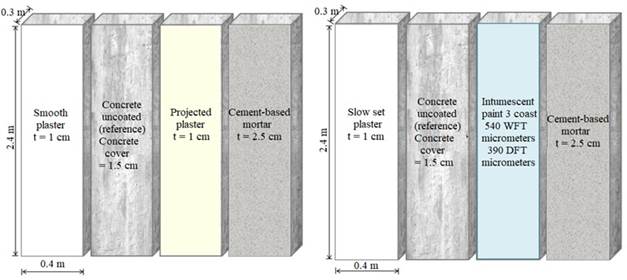
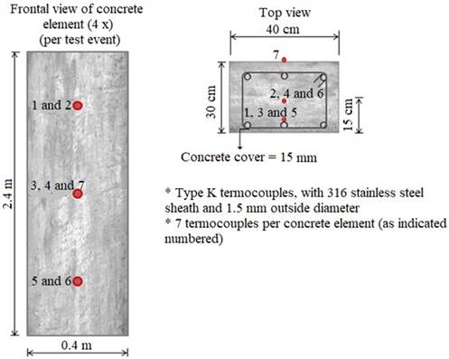
Figure 2.
Detail of termocouples location for both test events.
In all, five types of fire protective coatings were tested: slow-set plaster (popular in Brazilian market) and smooth formulated plaster (both hand applied), industrialized cement-based mortar (prepared on site), intumescent paint and projected plaster (applied with industrial equipment). The slow-set plaster, smooth formulated plaster and projected plaster have different chemical compositions, as will be discussed below, depending on their origin.
2.1 Details of concrete elements construction and coating systems application
In September 2017, the formwork and reinforcement were assembled [(stirrups with hooks, according to Kodur (2005)], thermocouples installed, and the concrete elements themselves were constructed inside the shed provided by IPT, in São Paulo. Concrete was designed with type CP II-E-40 cement, quartz pit natural fine sand, gravel sand and limestone gravel. The water was set at 175 L/m³ and a plasticizer/water reducer admixture was used to get a consistency of 20 ± 3 cm, gauged by slump-test. As planned, only one concrete mixer truck was involved in the pouring of the eight elements, leaving no room for variation of the concrete material when analyzing the results of the experimental tests. The eight samples were constructed under the same conditions and with the same batches of materials (formwork, concrete, reinforcement and thermocouples). The concreting event was controlled and the samples were molded and tested, with compressive strengths of 20.2 MPa (7 days) and 25.6 MPa (28 days), respectively. The values obtained were compatible with the 25 MPa f ck predicted for 28-day age.
After the construction of the eight elements, a 6-month period of concrete hydration degree was waited for the application of fire protective coating systems (preparation of base and coating layer itself). During these six months the elements were stored inside the shed and protected with a non-adherent plastic tarp, just to prevent impregnation of dirt on the surface or other types of damage or even vandalism. In March 2018, as planned, all fire protective coatings were applied.
On the four elements related to the first test event, three types of coating were applied (in one of them, the reference one, no coating was applied): a) type M30 smooth formulated plaster, hand applied with a steel trowel; b) type P80 projected plaster, applied using M280 projection machine; and c) general purpose industrialized mortar, sold in 20 kg bags.
On the four elements related to the second test event, three types of coating were also applied (as in the first event, in one of the elements, the reference one, no coating was applied): a) slow-set plaster, hand applied with a steel trowel; b) intumescent paint, type CKC-333; and c) general purpose industrialized mortar, sold in 20 kg bags.
Both the hand applied plaster and the projected plaster were applied with a thickness of 1.0 cm, controlled using a digital caliper and a thickness jig. The intumescent paint was applied in three coats totaling a wet thickness of 540 micrometers, term internationally known as WFT (Wet Film Thickness), which corresponds to 390 micrometers dry thickness, term known as DFT (Dry Film Thickness).
The coating layers themselves were applied approximately 15 days after the preparation of the roughcast mortar [rolled for plaster and troweled for mortar], following the deadlines that commonly occur on site. From March 2018 to the end of August 2018, the elements were kept uncovered within IPT shed in order to promote enough hydration degree of the coatings, as in a normal work situation, as shown in Figure 3.
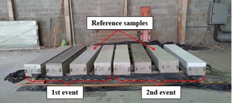
Figure 3.
Detail of the finished elements with coatings applied, except for the reference samples.
2.2 Details of the fire simulation tests
The fire simulation tests were carried out in the furnace of the Fire and Explosion Safety Laboratory of the Institute of Technological Research of São Paulo (IPT-SP), a center of excellence in technology in Brazil and a reference in this type of test, with dimensions that meet the planned thermal program. The furnace used in the experimental program has a system with five natural gas burners, arranged on both side walls and positioned so that there is no frontal encounter between them.
2.2.1First test event (1st event)
The four elements of the first test event were tested at once, unloaded and basically with one face exposed to fire (the largest face, 40 cm wide and 2.40 m high), in order to evaluate the influence of the coating without any interference. This also allowed the rear face (where the thermocouples were installed) to remain freely accessible during the fire simulation test. Prior to the test, after 11 months of the elements’ construction, control specimens were tested again, and a compressive strength of 30.4 MPa was found. On August 30th, 2018, the first fire simulation event was carried out, under the ISO 834 curve, for 120 minutes. Table 1 shows the maximum and average temperature values detected by the thermocouples located on the reinforcement, in each of the specimens, at 120 min of test.
| Table 1. Temperatures of thermocouples positioned on the reinforcement (concrete cover region), at 120 min of test. | ||||||||||
| Specimen | Temperatures (ºC) | |||||||||
|---|---|---|---|---|---|---|---|---|---|---|
| Maximum (thermocouple indicated) |
Average (thermocouples 1, 3 and 5) |
|||||||||
| Reference (uncoated) | 553 (thermocouple 1) | 543 | ||||||||
| Industrialized cement-based mortar coating (25mm) | 198 (thermocouple 3) | 195 | ||||||||
| Smooth formulated plaster coating (10 mm) | 206 (thermocouple) | 186 | ||||||||
| Projected plaster coating (10 mm) | 283 (thermocouple) | 231 | ||||||||
24 hours after the end of the test, the furnace was opened for visual inspection of the elements. Surface spalling was observed, uniformly distributed on the face of the reference element. No reinforcement exposure was detected. Partial fall of the coatings was verified on the other elements, but no superficial damage to the concrete, as shown in Figure 4.
The smooth formulated plaster sample still had some coating remaining upon the furnace opening (without any integrity or adhesion), an amount of 46% of the total area exposed to the fire. For the cement-based mortar sample, this number was 41%. Carefully investigating the elements using a hammer, it was found that the remaining coatings of smooth formulated plaster and mortar were completely friable and the remaining part almost spontaneously displaced, however, the roughcast mortar applied as adhesion was intact in both elements.
Notably, the sample coated with projected plaster still had part of the plaster adhered (in 100% of the sample), partially intact and with little hollow sound. However, there was not enough integrity for a pullout test by conventional methods, as the sample could easily be removed by mechanical scraping. It was found that the remaining layer was working only as a sacrificial layer (physical barrier) and with poor adherence. Using a digital caliper, it was verified that a delamination of the projected plaster occurred, with a thickness of the order of 5 mm and remaining in the concrete sample a thickness of the order of 6 mm (1 mm deviation from the original predicted thickness of 10 mm).
The reference sample, uncoated, also caught attention for the small amount and depth of spalling, corresponding to an area of the order of 19% of the original sample at a typical (maximum) depth of about 6 mm (measured at several points). In other words, even in the uncoated reference element, there was no exposure of the reinforcement (which had a 15mm concrete cover). In fact, there was no exposure of the reinforcement in any element tested in this first event.
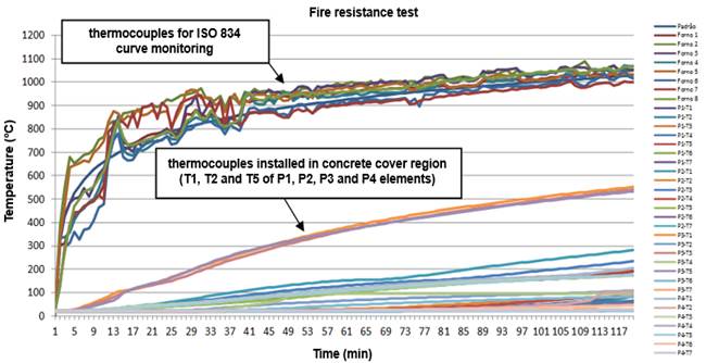
The temperature evolution obtained inside the samples confirmed the visual and qualitative analysis of the fireproof coatings’ performance. As observed in Figure 5, the heat distribution was uniform within the samples, according to the depth of each thermocouple. It is also noted that the three thermocouples located in the concrete cover region of the reference element differ greatly from the rest.
 |
||||
| Figure 5. Temperatures obtained inside the furnace and inside the elements of 1st event. | ||||
2.2.2 Second test event (2nd event)
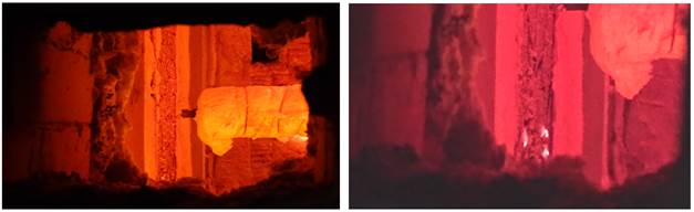
On September 5th, 2018, the second fire simulation event occurred, under the ISO 834 curve for 120 minutes. After 53 minutes of testing, it was already observed the flaking of all the slow-set plaster coating, quite different from what occurred in the first test event, taking part of the concrete adhered. Also, at 6 minutes of testing, the intumescent paint started to act. During this period, we also noticed the beginning of small flaking points of the reference element, without coating. At 20 minutes, the intumescent paint had a darker-colored “red-hot element” appearance and small incandescent spots, as shown in Figure 6. Table 2 shows the maximum and average temperature values of the thermocouples located on the reinforcement in each of the specimens at 120 min.
| Table 2. Temperatures of thermocouples positioned on the reinforcement (concrete cover region), at 120 min of test. | ||||||||||
| Specimen | Temperatures (ºC) | |||||||||
|---|---|---|---|---|---|---|---|---|---|---|
| Maximum (thermocouple indicated) |
Average (thermocouples 1, 3 and 5) |
|||||||||
| Reference (uncoated) | 557 (thermocouple 3) | 533 | ||||||||
| Industrialized cement-based mortar coating (25mm) | 255 (thermocouple 3) | 241 | ||||||||
| Intumescent paint coating (540 micrometers WFT / 390 micrometers DFT) | 386 (thermocouple 5) | 359 | ||||||||
| Slow-set plaster coating (10 mm) | 559 (thermocouple 1) | 487 | ||||||||
24 hours after the end of the test, the furnace was opened for visual inspection of the elements. Surface spalling was observed, uniformly distributed on the reference element face exposed to fire. No reinforcement exposure was detected.
In the element coated by the slow-set plaster, a large spalling / flaking was observed at its top, and no trace of the roughcast mortar applied as adhesion, as well as 100% of detachment of the plaster coating itself.
In the element coated with cement-based mortar, all the roughcast mortar kept adhered in the element and the coating itself detached almost entirely. Finally, the intumescent paint was detected covering the entire face of its concrete element, expanded and white colored, without exposing the concrete surface or reinforcement, as shown in Figure 7.
Carefully investigating the elements with the use of a hammer, it was found that, in the sample coated by slow-set plaster, besides the large spalling with reinforcement exposure, there was a friable layer with no strength in almost all the area exposed to fire (on the concrete surface). In the reference sample, the material still adhered to the surface was also friable throughout the covering region. Nevertheless, the roughcast mortar applied as adhesion of the mortar-coated element and the concrete surface of the intumescent paint-coated element were intact.
To summarize, the concrete was completely intact and preserved in the case of the elements coated with cementitious mortar and intumescent paint, showing no signs of a typically friable material or exposed reinforcement. The spalling area of the sample coated with slow-set plaster, where the reinforcement exposure occurred, was measured with a measuring tape, representing approximately 20% of the total area, suggesting that the slow-set plaster coating detached from the surface much before that observed in the 1st event and did not protect the concrete substrate.
 |
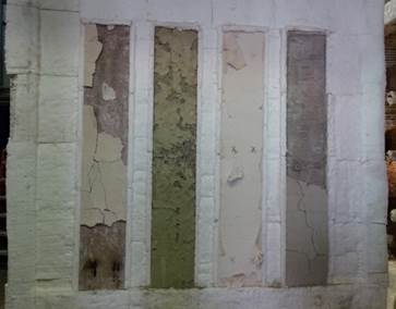
||||
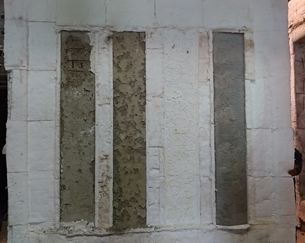
| Figure 7. Detail of the elements and coatings condition after furnace opening (event 2): slow-set plaster coating, reference element, intumescent paint coating and cement-based mortar coating. | ||||
Also, among all the reinforcement from the face exposed to fire, it was verified that only 6% was actually exposed. Notably, the intumescent paint-coated sample protected the concrete element well, with no indication of flaking. The surface was so completely well-finished that, in the case it had been clean, it could hardly be said that it had been subjected to a fire simulation test.
Using a digital caliper, it was found that there was severe spalling in the slow-set plaster coated sample, from 19 mm to 27 mm (maximum), over an area of approximately 20% of the total sample area (60 cm x 30 cm), as shown in Figure 7. The remaining friable part, in turn, had a thickness of the order of 2 mm to 3 mm (Figure 7), which was smaller than the reference sample one in of both events, as will be noted below.
In turn, the reference sample also drew attention for the small amount and depth of spalling. The flaking corresponded to an area of the order of 40% of the original sample in a typical (maximum) depth of about 7.5 mm (measured at several points) only, although the sample had turned friable in 100% of the area exposed to fire in this same measured depth. In other words, there was no exposure of the reinforcement (with minimum coverage of 15 mm). In fact, there was only reinforcement exposure in the slow-set plaster coated element at the second test event (underperforming the reference sample, uncoated). The expansion of the remaining intumescent paint, along its entire area exposed to fire, was also measured. In this case, it had no adhesion and was easily removed with a spatula (manually). From the scraped area, it was possible to measure with a caliper an expandability of 110 mm to 112 mm, which corresponds to the order of 30 times the original applied thickness of 390 micrometers dry (DFT), according to the manufacturer's specifications.
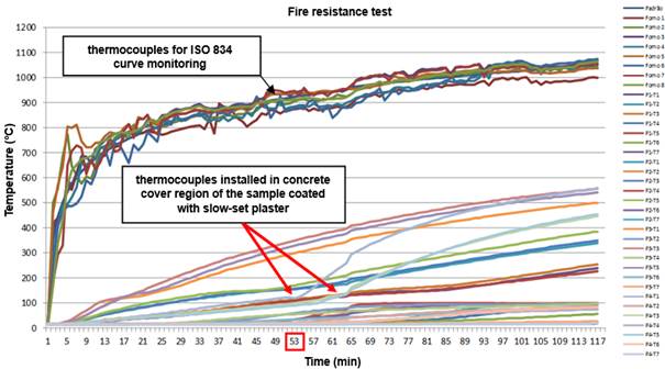
The evolution of temperatures obtained inside the samples also confirmed the visual and qualitative analyzes of the performance of the fireproof coatings. As observed in Figure 8, the heat distribution was uniform within the sample according to the depth of each thermocouple. A substantial increase in temperature was also noted in the three thermocouples of the reference sample in the concrete cover region, as well as in the three for slow-set plaster coated sample, from 53 min (highlighted in red), probably when the total detachment of this coating took place, taking with it part of the concrete and exposing the reinforcement. This behavior differs greatly from the exhibited by the rest of the thermocouples.
 |
||||
| Figure 8. Temperatures obtained inside the furnace and inside the elements of 2nd event. | ||||
Although the reinforcement was not exposed to fire by spalling in the region of thermocouples 3 and 5, under these conditions (after spalling), for approximately 65 minutes, due to the thermal conductivity of the steel, the temperature of the reinforcement measured at these points was only 20% lower than in the exposed region. It was expected to be 66% lower, if compared to the first test event involving smooth formulated plaster, where there was no spalling.
3. Results discussion and complementary tests
In general, it can be said that all the elements, except for the slow-set plaster sample (which was analyzed separately by complementary examinations), presented good performance when exposed to fire for 120 min (2 h). The concrete practically maintained its original integrity in the coated elements and presented damage (spalling / flaking) lower than 7.5 mm depth in the reference samples for a concrete coverage of only 15 mm (not exposing the reinforcement). In these reference samples, despite an initial flaking measured between 19% and 40% of the total area, after percussion hammer inspection, it can be safely stated that all the area exposed to fire was completely friable at the same depth, that is, in terms of integrity, about 6 mm depth of damage was verified in the reference sample of the first event and the order of 7.5 mm in the second event. These values are considered irrelevant to the 2 h test under the ISO 834 curve.
Also, regarding the measured temperatures (in the reference samples), there are a lot of similarities between the two test events, as it can be seen in Figures 5 and 8 (maximum 10 °C difference). In this case, on the average of the two test events, it can be stated that 15 mm of concrete cover thickness (without any coatings) was enough to record a temperature below 550 °C (on average 538 °C), for a temperature of almost 1000 °C in the furnace within 120 minutes of testing. That is, the 15 mm cover insulated a temperature of the order of 450 ºC, without any reinforcement exposure for a maximum flaking of 7.5 mm with the rest of the cover (about 50%) still quite intact, as exposed in Table 3.
Table 3.
Performance comparison of each type of coating in insulating the average temperature in thermocouples 1, 3 and 5, positioned in the reinforcement (cover region), at 120 min of test (regarding the reference element).
Test event
Samples in comparison
Average temperature (ºC)
Difference
Isolation
Event 1
Reference (uncoated)
543
348
64%
Cement-based industrialized mortar coating (25 mm)
195
Reference (uncoated)
543
357
66%
Smooth formulated plaster coating (10 mm)
186
Reference (uncoated)
543
312
57%
Projected plaster coating (10 mm)
231
Event 2
Reference (uncoated)
533
292
55%
Cement-based industrialized mortar coating (25 mm)
421
Reference (uncoated)
533
174
33%
Intumescent paint coating (540 micrometers WFT / 390 micrometers DFT)
359
Reference (uncoated)
533
46
9%
Slow-set plaster coating (10 mm)
487
Specifically on the cement-based mortar coatings, it was noted that probably, because of the temperatures obtained, they detached from the roughcast mortar base, either at the end or even after the end of the test, during natural cooling (the furnace was opened 24 h after the end of the test). Interestingly, the roughcast mortar applied directly to the concrete element (with 8mm x 8mm toothed trowel) was completely adhered and intact, providing an absolutely intact concrete in both samples coated with this system. In this context, the 2.5 cm thick mortar coating worked well as a sacrificial layer during the two test events. The temperatures measured within the sample corroborate these considerations. The graphs in Figures 5 and 8 show a linearity in the evolution of the measured temperature values, which is consistent with an interference-free heat transmission, i.e., no flaking during the test event (even considering the coatings in this case). An anomalous behavior, for example, a peak or a discontinuous temperature growth rate, could indicate localized flaking or even reinforcement exposure. It would greatly increase the measured temperature values, with a much faster heating rate compared to concrete one, because of the significant difference in the thermal conductivity of these two materials.
In the case of intumescent paint, it could be seen that it quickly started expanding itself in the first minutes of the test event, which was expected because the action of this type of chemical reaction starts at approximately 200 °C (the ISO 834 curve reaches 550 °C within the first five minutes). What was striking in this case is that only the thickness of 390 micrometers (three coats / DFT) was enough to guarantee the complete integrity of the structural element, keeping the original sample surface completely preserved. Despite the impression of “red-hot element” and signs of incandescence, there was no damage in 100% of the area exposed to fire, although with internal measured temperatures higher than those registered in the mortar coating, for example.
What caught attention and motivated complementary chemical tests and examinations were the analyzes of the plaster coated samples’ integrity. In the first event, it was found that the smooth formulated plaster applied with steel trowel completely preserved the integrity of the concrete element, including clear signs of the still adhered rolled roughcast mortar base. In this case, it is assumed that the same effect of the mortar coatings occurred, that is, the plaster must have detached from the roughcast mortar at the end or even after the end of the test, during natural cooling, providing an absolutely intact concrete in the sample coated with this system. In this context, only 1.0 cm of smooth formulated plaster coating worked well as a sacrificial layer.
In turn, in this same event, the projected plaster presented a delamination of the order of 50% of its thickness. This also greatly preserved the integrity of the concrete sample, which was still protected by approximately 6 mm of plaster. On the other hand, this remaining plaster had little adhesion and had a hollow sound and fluffy surface when subjected to steel hammer percussion tests. This leads to believe, even from the internal temperatures, that the delamination actually occurred during the fire simulation test (from inspections carried out, within 30 to 40 minutes after the start of the test). That is, for a period of 80 to 90 minutes of testing, this element had only been protected by 6 mm of projected plaster thickness. It is interesting to compare these considerations with the recorded temperature values. Despite a remaining plaster thickness after completion of the test, the internal temperatures were slightly higher when compared to the smooth formulated plaster sample, which suggests that there was even a delamination during the test and that a smaller thickness functioned as a layer of sacrifice. At 120 minutes of testing, an average of 231 °C was recorded in the projected plaster-coated element, approximately 25% higher when compared to the smooth formulated plaster (186 °C). We remember that they are materials of the same nature, including very similar chemical, mineralogical and thermal composition, which corroborates with the earlier delamination in the projected plaster (perhaps due to the application method) and the preservation of the smooth formulated plaster throughout the period of the first test event (detachment only after furnace cooling).
Specifically on slow-set plaster coating applied in the second test event, with the same procedures as the smooth formulated plaster (first event), it was noted that there was a significant difference in the results obtained, represented by a severe spalling of concrete, with reinforcement exposure. It was the only sample with reinforcement exposure, among the eight tested in both test events. It is noteworthy that there was no spalling in the uncoated (reference) samples. The observed spalling had an approximate area of 60 cm x 30 cm, with a maximum depth of 27 mm, which was enough to expose the reinforcement, that had a 15 mm covering. Nevertheless, among total area of reinforcement that could be exposed, only 6% was actually exposed.
Based on the monitored temperatures, it is believed that the highest proportion spalling occurred between 40 and 50 minutes, since the behavior of the internal temperature evolution in the covering region changed dramatically at approximately 55 minutes. The behavior up to 55 minutes was very similar to that of the first test event plaster samples. From that moment on, there was a sudden change in the internal heating rate, recorded mainly by thermocouple 1 and later in the other thermocouples, which leads us to believe that the detachment of the coating system had already occurred, with reinforcement exposure and a change in the records, due to thermal conductivity of the steel (the first thermocouple line was fixed on the boundary longitudinal reinforcement concrete cover). The average temperature measured in the three thermocouples was 487 ºC, with a maximum of 559 ºC, that is, almost the same temperature as the reference samples, which presented peaks of 553 ºC and 557 ºC in the two test events, respectively.
As the experimental study was designed to have as few variables as possible [elements built at the same time, with the same concrete, procedures and manpower; same worker applying the troweled plaster coatings (smooth formulated and slow-set plaster, regardless of origin) on the elements, fire simulation tests under the same conditions etc.)], it was assumed that the agent responsible for the anomalous behavior could be related exclusively to the material applied (slow-set plaster popular in the market). That said, it was decided to elaborate and carry out a plan of tests and complementary chemical and thermal exams in the three samples of plaster involved in the experimental study: M30 smooth formulated plaster, P80 projected plaster and slow-set plaster popular in the market.
Samples from the same batch of plaster used in the experimental study were collected and separated in order to identify any alteration, impurity or strange material. Results from the semiquantitative chemical analysis have already indicated a significant difference in “Loss on ignition” and “Sulfuric Anhydride”, as shown in Table 4.
| Table 4. Results from the X-ray fluorescence semiquantitative chemical analysis. | ||||||||||
| Determinations | Results, in % | |||||||||
|---|---|---|---|---|---|---|---|---|---|---|
| slow-set plaster popular in the market | P80 projected plaster | M30 smooth formulated plaster | ||||||||
| Loss on ignition (LOI) | 20,9 | 9,5 | 9,5 | |||||||
| Sulfuric anhydride (SO3) | 39,8 | 51,8 | 53,7 | |||||||
| Calcium oxide (CaO) | 32,5 | 32,2 | 31,2 | |||||||
| Aluminum oxide (Al2O3) | 2,3 | 1,7 | 0,8 | |||||||
| Magnesium oxide (MgO) | 2,2 | 0,1 | 0,2 | |||||||
| Silicic anhydride (SiO2) | 1,9 | 3,6 | 3,4 | |||||||
| Phosphorus oxide (P2O5) | 0,2 | 0,2 | 0,5 | |||||||
| Ferric oxide (Fe2O3) | 0,1 | 0,2 | 0,2 | |||||||
| Strontium oxide (SrO) | 0,1 | 0,1 | 0,2 | |||||||
| Potassium oxide (K2O) | n.d. | 0,4 | 0,4 | |||||||
In the slow-set plaster sample, the value obtained for fire loss differed by 120% and sulfuric anhydride about 35% when compared to the smooth formulated and projected plaster samples of the first test event, which in turn were quite high similar. In the case of sulfuric anhydride, it is noted that the value obtained in the test was still 25% below the limit required in the standard ABNT NBR 13207:2017 - Plaster for construction - Requirements, i.e. the sample sold in the market does not follow the limits prescribed by national standards. Concomitantly, thermogravimetric analysis (TG / DTG) (differential thermal and simultaneous thermogravimetric analysis) were performed to identify the mass losses, where the fire loss values were confirmed with minimal differences from those obtained in the X-ray fluorescence semiquantitative chemical analyzes, as shown in Table 5.
| Table 5. Mass losses from TG / DTG curves. | ||||||||||||
| Material | Mass loss as a function of temperature range | Total loss (%) | ||||||||||
|---|---|---|---|---|---|---|---|---|---|---|---|---|
| Slow-set plaster | ºC | 28-69 | 69-168 | 168-1000 | 20,0 | |||||||
| % | 0,73 | 3,46 | 15,8 | |||||||||
| Interpretation of mass losses as a function of temperature range: | ||||||||||||
| 1. 23 – 82ºC: beginning of free water loss; | ||||||||||||
| 2. 82 – 211ºC: end of free water loss and adsorption water; | ||||||||||||
| 3. 211 – 934ºC: decarbonation of carbonated phases; | ||||||||||||
| 4. 934 – 1000ºC: probable beginning of sulfur loss. | ||||||||||||
| Smooth formulated Plaster M30 | ºC | 28-78 | 78-253 | 253-300 | 300-934 | 934-1000 | 8,63 | |||||
| % | 1,60 | 5,15 | 1,61 | 1,58 | 0,27 | |||||||
| Interpretation of mass losses as a function of temperature range: | ||||||||||||
| 1. 28 – 78ºC: beginning of free water loss; | ||||||||||||
| 2. 78 – 253ºC: end of free water loss and adsorption water; | ||||||||||||
| 3. 253 – 300ºC: mass gain. Probable oxidation of metallic elements present in Ankerite; | ||||||||||||
| 4. 300 – 934ºC: decarbonation of carbonated phases; | ||||||||||||
| 5. 934 – 1000ºC: probable beginning of sulfur loss. | ||||||||||||
| Projected plaster P80 | ºC | 28-82 | 82-211 | 211-934 | 934-1000 | 8,70 | ||||||
| % | 1,60 | 5,15 | 1,61 | 0,34 | ||||||||
| Interpretation of mass losses as a function of temperature range: | ||||||||||||
| 1. 23 – 82ºC: beginning of free water loss; | ||||||||||||
| 2. 82 – 211ºC: end of free water loss and adsorption water; | ||||||||||||
| 3. 211 – 934ºC: decarbonation of carbonated phases; | ||||||||||||
| 4. 934 – 1000ºC: probable beginning of sulfur loss. | ||||||||||||
The high fire loss in the slow-set plaster sample, confirmed by two test methods [X-ray fluorescence semiquantitative analysis and thermogravimetric analysis (TG / DTG) (differential thermal and simultaneous thermogravimetric analysis)] can be associated with the high volume of CO2 released by the thermal decomposition of the carbonates (dolomite and calcite), as will be verified in the analyzes below. Also, in order to identify any difference that could justify the anomalous behavior of the slow-set plaster coating, semi-quantitative mineralogical X-ray diffraction analyzes were performed, as shown in Table 6.
| Table 6. Results of semi-quantitative mineralogical analyzes of the phases analyzed by X-ray diffraction. | ||||||||||
| Material | Compounds or mineralogical phases | Molecular formula | Results (%) | |||||||
|---|---|---|---|---|---|---|---|---|---|---|
| Slow-set plaster | Bassanite | CaSO4.½H2O | 65,2 | |||||||
| Dolomite | CaMg(CO3)2 | 22,5 | ||||||||
| Calcite | CaCO3 | 5,5 | ||||||||
| Anhydrite | CaSO4 | 2,0 | ||||||||
| Alpha-Quartz | α SiO2 | 1,1 | ||||||||
| Hornblende | Si14,56Al2,00Mg6,98Fe2,66Ti0,12 Ca3,32Na1,25Mn0,04K0,03H4,00O47,60F0,40 | 1,0 | ||||||||
| Olivine | Fe0,145Mg1,854SiO4 | 0,8 | ||||||||
| Chrysotile | Mg3(Si2O5)(OH)4 | 0,7 | ||||||||
| Ankerite | CaFe0,23Mg0,77(CO3)2 | 0,7 | ||||||||
| Zeolite | SiO2 | 0,5 | ||||||||
| Projected plaster P80 | Bassanite | CaSO4.½H2O | 93,2 | |||||||
| Anhydrite | CaSO4 | 4,3 | ||||||||
| Dolomite | CaMg(CO3)2 | 1,3 | ||||||||
| Calcite | CaCO3 | 0,6 | ||||||||
| Gypsum | CaSO4.2H2O | 0,4 | ||||||||
| Olivine | CoMg7(SiO4)4 | 0,1 | ||||||||
| Quartz | SiO2 | < 0,1 | ||||||||
| Smooth formulated plaster M30 | Bassanite | CaSO4.½H2O | 88,9 | |||||||
| Anhydrite | CaSO4 | 7,1 | ||||||||
| Ankerite | Ca3,15Fe1,89Mg0,81Mn0,15(CO3)6 | 1,2 | ||||||||
| Dolomite | CaMg(CO3)2 | 1,1 | ||||||||
| Calcite | CaCO3 | 1,2 | ||||||||
| Gypsum | CaSO4.2H2O | 0,6 | ||||||||
| Alpha-Quartz | α SiO2 | < 0,1 | ||||||||
To summarize, it was observed a large difference in the slow-set plaster sample when compared to the smooth formulated and projected plaster, mainly in the contents of bassanite and dolomite.
Thus, it is believed that the presence of a higher carbonate content (dolomite and calcite), identified in high proportions in the thermal decomposition of the slow-set plaster sample, will certainly generate a significant volume of carbon dioxide, which combined with a rapid heating rate environment and excessive furnace temperatures (characterized by the ISO 834 curve), will generate larger expansion pressures, resulting in severe spalling, including reinforcement exposure. In other words, we believe that if the slow-set plaster sample complied with the minimum requirements of current standardization (free of high carbonate content), the fire behavior of plaster coatings would be very similar. Thus, it is important to characterize the properties of the plaster which, as observed, has a unique behavior and greatly interferes in the performance of the coating when used with fireproof purposes.
4. Conclusions
References
Alexander, B. (1982). Behaviour of gypsum and gypsum products at high temperatures. RILEM Committee PHT-44, British Gypsum, East Leake, Loughborough, England.
Almeida, D. F. (1984). As estruturas de concreto armado e o fogo, comportamento, consequências, restauração. Dissertação (mestrado) - Escola Politécnica, Universidade de São Paulo, São Paulo.
Associação Brasileira de Normas Técnicas (1980). NBR 5627: Exigências particulares das obras de concreto armado e protendido em relação à resistência ao fogo. Rio de Janeiro, 3 p.
Associação Brasileira de Normas Técnicas (2014). NBR 6118: Projeto de estruturas de concreto, procedimentos. Rio de Janeiro, 238 p.
Associação Brasileira de Normas Técnicas (2017). NBR 13207: Gesso para construção civil - Requisitos. Rio de Janeiro, 3 p.
Associação Brasileira de Normas Técnicas (2001). NBR 14432: Exigências de resistência ao fogo de elementos construtivos de edificações, Procedimento. Rio de Janeiro, 14 p.
Associação Brasileira de Normas Técnicas (2012). NBR 15200: Projeto de estruturas de concreto em situação de incêndio. Rio de Janeiro, 48 p.
Atefi, H., Nadjai, A., Ali, F. (2017). Numerical and experimental investigation of the thermal behaviour of coated cellular beamns with intumescent coatings at elevated temperatures. In: IFireSS 2017 - 2nd International Fire Safety Symposium. Naples, Italy, June 7-9. p. 257-264.
Kodur, V. K. R. (2005). Guidelines for fire resistance design of high-strength concrete columns. Ottawa, Ontário, Canadá: IRC/NRC. (Report NRCC-47729). Disponível em: http://irc.nrc-cnrc.gc.ca/pubs/fulltext/nrcc47729/ . Acesso em: novembro de 2007.
Landi, F. R. (1986). Ação do incêndio sobre as estruturas de concreto armado. Boletim técnico nº 01/86. São Paulo: Escola Politécnica, Universidade de São Paulo. 24p.
Lucherini, A., Maluk, C. (2017). Novel test methods for studying the fire performance of thin intumescent coatings. In: IFireSS 2017 - 2nd International Fire Safety Symposium. Naples, Italy, June 7-9. p. 565-572.
Malhotra, H. L. (1982). Properties of Materials at High Temperatures — Report on the work of technical committee 44-PHT. Materials and Structures/Matériaux et Constructions. Vol. 15. N° 86. RILEM, Paris.
Ogrin, A., Saje, M., Hozjan, T. (2017). Effect of incomplete expansion of intumescent coating on mechanical response of steel frame in fire. In: IFireSS 2017 - 2nd International Fire Safety Symposium. Naples, Italy, June 7-9. p. 365-372.
Silva, D., Bilotta, A., Nigro, E. (2017). Experimental analysis on the effectiveness of intumescent coatings in fire. In: IFireSS 2017 - 2nd International Fire Safety Symposium. Naples, Italy, June 7-9. p. 249-256.
Silva, V. P. (2012). Projeto de estruturas de concreto em situação de incêndio, conforme ABNT NBR 15200:2012. São Paulo: Blucher.