
| Review | https://doi.org/10.21041/ra.v10i1.421 |
Fire impacts on concrete structures. A brief review
Acciones y efectos nocivos del fuego sobre estructuras de concreto. Una breve reseña
Ações e efeitos deletérios do fogo em estruturas de concreto. Uma breve revisão
C.
Britez1
*, M. Carvalho2, P. Helene3
![]()
1 Pesquisador de Pós-Doutorado na Escola Politécnica da USP, Britez Consultoria, São Paulo, Brasil.
2 Universidade Presbiteriana Mackenzie, São Paulo, Brasil.
3 Professor Titular da Escola Politécnica da USP, PhD Engenharia, São Paulo, Brasil.
* Contact author: britez.consultoria@gmail.com
Received: 07 June 2019
Accepted: 11 November 2019
Published: 30 December 2019.
| Cite as: Britez, C., Carvalho, M., Helene, P. (2020), "Fire impacts on concrete structures. A brief review", Revista ALCONPAT, 10 (1), pp. 1 –21, DOI: http://dx.doi.org/10.21041/ra.v10i1.421 |
ABSTRACT
This paper aims to present briefly discuss some essential topics about the impact of fire on concrete structures and the possible deleterious effects of high temperatures on the concrete material itself. A literature review was conducted, addressing the behavior of concrete (seen as a material and as a structural element) when exposed to exceptional and severe actions from a fire scenario, contributing to demystify some beliefs and doubts about the spalling phenomenon and the behavior of reinforced concrete under fire situations.
Keywords:
fire,
concrete structure,
spalling.
RESUMO
Este artigo tiene como objetivo presentar y discutir brevemente algunos temas esenciales sobre la acción del fuego en las estructuras de concreto y los posibles efectos nocivos de las altas temperaturas en el material concreto. Se realizó una revisión de la literatura, que aborda el comportamiento del concreto (visto como un material y como un elemento estructural) cuando se expone a acciones térmicas excepcionales y severas de un escenario de incendio, lo que contribuye a desmitificar algunas creencias y dudas sobre el fenómeno de ocurrencia de spalling y el comportamiento de la estructura de hormigón armado en situación de incendio.
Palavras-chave:
incêndio,
estrutura de concreto,
spalling.
RESUMEN
Este artículo tiene como objetivo presentar y discutir brevemente algunos temas esenciales sobre la acción del fuego en las estructuras de concreto y los posibles efectos nocivos de las altas temperaturas en el material concreto. Se realizó una revisión de la literatura, que aborda el comportamiento del concreto (visto como un material y como un elemento estructural) cuando se expone a acciones térmicas excepcionales y severas de un escenario de incendio, lo que contribuye a desmitificar algunas creencias y dudas sobre el fenómeno de ocurrencia de spalling y el comportamiento de la estructura de concreto armado en situación de incendio.
Palabras clave:
fuego,
estructuras de concreto,
spalling.
1. Introduction
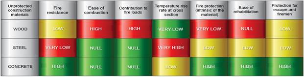
In terms of the design of structures and of the exceptional action of fire, when compared to other (unprotected) building materials, concrete has a number of attributes, as it can be seen in Figure 1. In this context, it is emphasized that there are two main components responsible for the positive performance of concrete in fire conditions: the first related to the intrinsic properties of the material and the second to its functionality when inserted in the overall structure.
 |
||||
| Figure 1 Summary of the performance of (unprotected) building materials under fire (translated from Jacobs, 2007). | ||||
Concrete is non-combustible and has a low temperature rise rate along its cross section, so in most structural systems the material can be used without any additional fire protection.
In this article, some essential topics about the action of fire on concrete structures and the possible deleterious effects of high temperatures on the concrete material itself are briefly presented and discussed.
2. Aspects of concrete under fire situation
2.1 Fire, concrete and burning event
In Brazil, ABNT NBR 13860:1997 has the following definition: “Fire is the combustion process characterized by the emission of heat and light” . However, according to Seito et al. (2008), despite major advances in fire science, there is still no global consensus to define fire because there is no clear agreement on the definitions of major international standards in force.
Seito et al. (2008) clarifies that a theory known as the Fire Triangle was initially formulated, which was formed by three fundamental elements: the fuel, the oxidizer (oxygen) and the heat. According to this theory, the removal of any of these elements from the triangle would be directly responsible for extinguishing the fire.
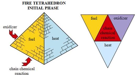
On the other hand, with the discovery of the halon extinguishing agent1, the theory was reformulated, being known today as Fire Tetrahedron (Figure 2). In turn, the Fire Tetrahedron consists of the following elements: heat, oxidizer, fuel and chain reaction.
Heat is the element used to start a fire, maintain and increase its spread. Oxidizer (oxygen) is required for combustion and is present in the air surrounding us. Fuel is the propagating element of fire and can be solid, liquid or gaseous. The chain reaction makes the burning process self-sustaining. Basically, the radiated heat from the flames reaches the fuel and it is broken down into smaller particles, which combine with oxygen and burn, radiating heat back into the fuel, thus forming a constant (self-sustaining) cycle.
 |
||||
| Figure 2 Fire tetrahedron (adapted from Seito et al., 2008). | ||||
Concrete (exclusively as a material) is recognized for its good behavior at high temperatures due to its thermal characteristics such as: incombustibility and low thermal conductivity. In addition, concrete does not release toxic gases when heated and the elements have greater mass and volume when compared to other materials such as the elements of metal and wood structures, i.e. potentially resist longer.
It can be said, therefore, that concrete is not a fundamental element of Fire Tetrahedron because it is not a solid fuel. In a fire event, concrete suffers the consequences of the burning of any flammable material, whether solid, liquid or gaseous. Generally, in commercial and residential buildings, this flammable charge comes from solid cellulosic base materials such as doors, furniture, office supplies, carpeting, curtains, etc.
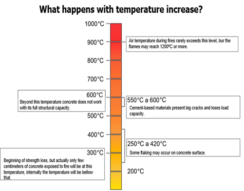
In general, several studies conservatively point out that a more exposed portion of concrete loses approximately 25% of its original compressive strength when heated at temperatures around 300ºC and approximately 75% when this temperature reaches 600ºC inside.
In addition to the reduction in strength, precursor research by Abrams (1971) and Neville (1981) indicated that concretes considered normal2 suffered high thermal gradients when exposed to fire and there was a strong tendency for hot surface layers to detach from the cooler layers inside the element. This type of detaching is known worldwide as spalling.
Fire generally starts in small proportions and its growth depends on the first ignited3 item, the fire performance characteristics of materials in the vicinity of this ignited item, and its distribution in the environment (Seito et al., 2008).
Costa & Silva (2003) and Costa (2008) describe that, in general, the curve that represents the temperature variation in a real fire is characterized by two well-defined branches (one ascending and one descending) with three phases delimited by two points (Figure 3): flashover4 and maximum temperature. These three phases are explained below.
- Ignition: heating stage at the beginning of the fire, with gradual temperature growth, with minimal influence of compartment characteristics and without risk to human life or heritage by structural collapse. This stage is also known as pre-flashover and ends at the instant known as flashover.
- Flashover: stage characterized by a sudden change in temperature growth. At this stage all combustible material in the compartment is combusted. The temperature of the hot gases is above the 300ºC level until reaching the peak of the curve, usually with temperatures above 1000ºC.
- Cooling: stage that represents the gradual temperature reduction of the gases in the environment, after the complete extinguishing of the combustible material present in the compartment. Without new fire loads to feed the flames, heat loss begins, i.e. the gradual cooling of the fire.
 |
||||
| Figure 3 Main phases of a real fire (Costa & Silva, 2003). | ||||
In general, the simulation of real or natural fire in a structure is quite complex and can be quite unique, as each fire has its particularities, which depend directly on the heating rate, the maximum temperature reached and the duration of the fire event.
Considering this situation, Costa & Silva (2003, 2006) observed that, to facilitate the determination of the thermal action in the structures, mathematical fire models were formulated to describe the variation of the room temperature as a function of the fire time.
The temperature-time relation, in these specific cases, can be represented by "temperature-time curves" or "fire curves", which are standardized and popularly known as the "standard fire curve".
2.2 Standard fire simulation curves
These are standard curves adopted in experimental and laboratory fire resistance tests to standardize the tests and provide enough support to analyze and compare the results, once the fire simulation was normalized (Costa e Silva, 2006).
In this perspective, when the minimum resistance time of the structural elements is determined by means of the standard fire curve, it is referred to as the Fire Resistance Required Time or simply by the acronym TRRF (ABNT NBR 14432 in Brazil: 2001).
TRRF is a standardized minimum period which assumes that a given structure will maintain its performance functions during a fire scenario simulated by a standard curve.
In general, this period is expressed in 30-minute intervals with predetermined values, depending on several factors (fib, 2007): type of occupation/use, height and number of floors of the building, number of people to be evacuated, room dimensions, escape routes/emergency exits and available protection systems (extinguishers, automatic showers, among others).
Figure 4 shows the temperature profiles that simulate three standard fire scenarios that are commonly used in experimental studies, as follows: (a) the tunnel fire scenario; (b) the one caused by hydrocarbon-based materials and (c) the one caused by buildings (by cellulosic materials).
 |
||||
| Figure 4 “Idealized” curves for three fire simulation scenarios: tunnels, hydrocarbons and buildings - cellulosic materials - up to 120 minutes (The Concrete Center, 2004). | ||||
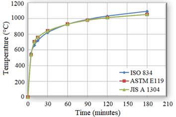
The three most widespread idealized and standardized curves in the technical field used in experimental studies involving fire scenario simulations caused by cellulosic-based materials in concrete elements are the curves: ISO 834, ASTM E119 and JIS A 1304 (Phan, 1996). These curves are very similar and can be seen, overlapping, in the Figure 5. Tunnel and hydrocarbon standard curves will not be addressed in this article and can be consulted in Leonardo Da Vinci Pilot Project: Handbook 5 (2005).
 |
||||
| Figure 5 Standard fire curves (adapted from Phan, 1996). | ||||
The ISO 834 curve is one of the most used in international experimental studies, being also adopted in Brazil - transcribed in ABNT NBR 5628:2001. This curve specifies that the sample must be subjected to a temperature rise inside the furnace, given by the following logarithmic equation:
 | (Equation 1) |
Where:
t = time, expressed in minutes (min);
θ = furnace inside temperature at time t, expressed in Celsius degrees (°C);
θ0 = initial temperature inside the furnace, expressed in Celsius degrees (ºC).
Other standard curves for flammable materials (ASTM E1549, RWS and RABT) have been modeled for fire severity and have been internationally recommended for special situations (Costa, 2008). There are also fire curves called “natural curves”, parameterized by the amount of combustible material (fire load), the degree of ventilation and the thermal and physical characteristics of the compartmental materials. These curves are simplified models of the real fire and will not be covered in this article and can be consulted in Leonardo Da Vinci Pilot Project: Handbook 5 (2005).
2.3 Temperature distribution inside the concrete
Heat is the energy that is being transferred from one system to another because of a temperature difference. Basically, there are three classic heat transfer mechanisms: conduction, convection, and radiation.
In conduction, thermal energy is transferred through interactions between atoms or molecules, although there is no transport of these atoms or molecules, only the displacement of energy. In convection, energy is transported in the form of heat through direct mass transport. In radiation, thermal energy is carried through space in the form of electromagnetic waves moving at the speed of light.
In a fire event there is a combination of these three heat transfer mechanisms, however, within the concrete mass there is a predominance of conduction heat flux.
In this context, the calculation of the development of a temperature field in the cross section of a structural concrete element exposed to fire involves solving the classical Fourier differential equation:
 | (Equation 2) |
In which:
λθ: is the thermal conductivity of the material (W/m ºC);
ρ.c: is the specific volumetric heat of the material (product of specific mass and absolute specific heat) (J/kg ºC);
x, y e z: the Cartesian coordinates of the three-dimensional system;
Q: is the internal heat rate generated on the material;
∂θ: is the temperature gradient in the direction of heat flow;
t: time (s).
Internal heat generation Q can be considered 0 (zero) for non-combustible materials (such as concrete). The boundary conditions (on the surface of the element) are expressed in terms of heat flow equations and the thermal properties of the material depend on the type and quantity of materials used in concrete mix design (Leonardo Da Vinci Pilot Project: Handobook 5, 2005).
To exemplify the behavior of the temperature field evolution as a function of time in a concrete element, we present the computer simulation study by Ongah, Mendis & Sanjayan (2002) in high strength concrete walls (Figure 6) with only one side exposed to fire. The graph indicates the significant thermal gradient inside the material (concrete) according to a heat flow model that numerically simulates the fire scenario.
 |
||||
| Figure 6 Temperature field evolution in a high strength concrete wall as a function of fire exposure time (Ongah, Mendis & Sanjayan, 2002). | ||||
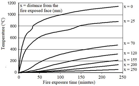
Another way to present the temperature evolution inside a concrete element, prescribed by the main international codes, can be seen in Figure 7. In this case, the instantaneous curves of standardized times as a function of the temperature and depth of the surface exposed to fire are presented, this is a very common model adopted by researchers and in the codes of various countries.
 |
||||
| Figure 7 Calculated temperature distribution as a function of the depth of surface exposed to fire and fire exposure time, by using a numerical model (Ongah, Mendis & Sanjayan, 2002). | ||||
2.4 Changes in microstructure of concrete material at high temperatures
Precise analysis of the behavior of changes in the microstructure of a concrete sample is considered quite complex, as each concrete has its uniqueness due to the vast alternatives of materials and available additions, as well as the use of different mix design techniques. It is also noteworthy that at high temperatures, anisotropy and concrete material heterogeneity become much more evident.
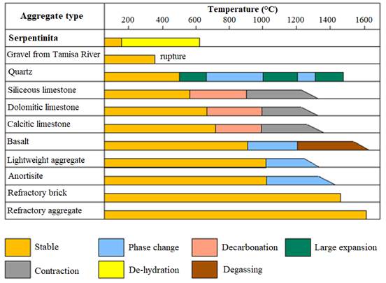
Obviously, some reactions are more striking given the prior knowledge of the lithological aspects of the aggregates, additions and the type of cement employed in concrete mix design. As specifically to the lithological nature of the aggregate, Figure 8 shows the marked difference in behavior (thermal stability) of various aggregates as a function of temperature increase.
In the context of microstructure, Taylor (1990) mentions that due to its low thermal conductivity and high specific heat, concrete provides good protection to steel in fire situation, however, it can be severely damaged due to thermal actions that harm mainly the cement paste. He highlights that at low temperatures, the cement paste expands when heated, but from 300ºC, a contraction occurs, associated with water loss. At this stage, aggregates continue to expand, and the resulting internal stresses can lead to loss of strength, cracking and flaking. Some phenomena are more explicit, quartz elements, for example, expand sharply at 573 °C due to a polymorphic transformation of crystallization and calcite contracts from 900 °C due to its generalized decomposition.
Taylor (1990) also describes the thermal effects on cement paste, and points out that: below 500ºC, carbonation and dilation of the matrix pores occur mainly; between 450 and 550ºC, the decomposition of C-S-H, and at 600ºC, the decomposition of CaCO3, providing CaO, which may eventually rehydrate during the cooling phase.
Specifically regarding the role of water, Kalifa et al. (2000) note that the excessive water contained in saturated Portland cement pastes contributes to the formation of significant pressure gradients in the concrete pore network during mass transfer (water evaporation) and, consequently, in the increase of cracking due to contraction of the paste.
 |
||||
| Figure 8 Behavior of various aggregates during heating (adapted from fib, 2007). | ||||
Regarding this, despite the significant physicochemical changes that occur in the cement paste, as well as the role of water in the mix, fib (2007) points out that at high temperatures it is the aggregates that can really govern the thermal behavior of concrete, when they are considered exclusively as a composite material. The main reasons for this theory are based on the following considerations:
- aggregates generally occupy a significant volume of concrete, between 60% and 80% of the volume of normal concrete;
- variations in aggregate properties during heating can have a significant effect on concrete performance at high temperatures. The thermal conductivity of concrete, for example, is greatly influenced by the lithological nature of the aggregate;
- each type of aggregate reacts differently to heat. The main factor in the behavior of heated concrete is the chemical and physical stability of the aggregate;
- aggregates are also responsible for restricting any expansion and contraction of the cement paste during heating.
In general, the physical-chemical process of concrete, involving the interaction between aggregates and cement paste, in a fire situation, can be simplified as shown in Figure 9.
 |
||||
| Figure 9 Physical-chemical process of concrete in fire situation (adapted from Jacobs, 2007). | ||||
As for reinforced concrete itself, Cánovas (1988) apudCosta (2008) notes that after 100ºC, the reduction in adhesion between steel bars and concrete may occur due to the increase and duration of heating, and that above 600ºC there may be a significant loss of adherence. It is noteworthy that the microstructural changes in the steel bars are not part of the scope of this article, but can be consulted in other references, namely: Holmes et al. (1982), Cabrita Neves, Rodrigues & Loureiro (1996) and Purkiss (1996).
2.5 Flaking of concrete at high temperatures (spalling)
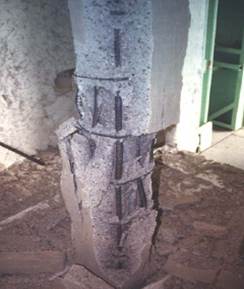
The term spalling is internationally known and standardized in leading international codes and research. The physical phenomenon known as spalling (Figure 10) can be defined as explosive, and for some even called violent/explosive, flaking of layers or concrete pieces from the surface of a structural element when exposed to high temperatures and rapid heating rates, both characterized by a fire scenario (fib, 2007).
 |
||||
| Figure 10 Example of explosive spalling occurred in high strength concrete column f ck = 83 MPa (Kodur, 2005). | ||||
It should be clarified, however, that spalling is not a mechanism of failure or structural collapse of the element. The phenomenon may be mild or severe and, as a result, may or may not lead to rapid loss of cross section, which could trigger a structural collapse mechanism, such as traditional failures caused by compression, flexion or shear.
The extent, severity and nature of spalling can be very variable and unpredictable. The phenomenon may be insignificant in quantity and consequence when small punctures occur; however, it can be severe and compromise the fire resistance of the element due to the peeling of large portions of concrete, exposing the reinforcement and decreasing its structural capacity due to the respective reduction of the cross section.
In order to simplify and classify the spalling phenomenon, fib (2007) proposed to group it into six categories, namely5:
- aggregate spalling;
- explosive spalling;
- superficial spalling;
- spalling per delamination;
- edge spalling and
- post-cooling spalling.
Of all categories explosive spalling is the most severe in a fire situation. As discussed in fib (2007), this type of spalling can result in explosive and subsequent breakdowns of concrete layers, generally reaching thicknesses between 25 and 100 mm, depending on each specific case.
According to Khoury & Anderberg (2000) and fib (2007), the occurrence of each type of spalling is influenced by several factors, such as strength, age, type and size of aggregates, moisture content and the water vapor permeability of the material; the maximum temperature and the heating rate of thermal actions; the shape and size of the cross section, the presence of cracks, the steel rate, the arrangement (configuration) of the reinforcement, the presence of polypropylene fibers and the loading intensity of the structural element. The influence of these factors can be briefly observed in Chart 1 6.
| Chart 1 Different categories of spalling and their respective influencing agents (fib, 2007). | |||||||||
|---|---|---|---|---|---|---|---|---|---|
| Spalling classification | Time of occurrence (probabilistic) | Nature | Sound aspects | Severity | Main influences* | ||||
| Aggregate | between 7 and 30 minutes | cracking | small pops (popcorn type) | superficial | H, A, S, D W | ||||
| Edge | between 30 and 90 minutes | nonviolent | none | may be severe | T, A, Ft, R | ||||
| Superficial | between 7 and 30 minutes | violent | occurrence of cracking/creaking | may be severe | H, W, P, Ft | ||||
| Explosive | between 7 and 30 minutes | violent | loud bangs / explosions | severe | H, A, S, Fs, G, L, O, P, Q, R, S, W, Z | ||||
| Delamination | when concrete becomes friable (loses strength capacity) | nonviolent | none | may be severe | T, Fs, L, Q, R | ||||
| Post-cooling | during and after moisture absorption cooling | nonviolent | none | may be severe | T, Fs, L, Q, R, W1, AT | *Theacronymsusedintheoriginaldocumentwerepreserved(fib,2007),accordingtothefollowingcaptiontoavoidconfusionwithacronymsalreadyusedinthenationallanguage(fromBrazil).
Subtitle: A = aggregate thermal expansion, D = aggregate thermal diffusivity, Fs = concrete shear stress, Ft = concrete tensile stress, G = concrete age, H = heating rate, L = load / restraint, O = heating profile, AT = aggregate type, P = permeability, Q = cross-sectional shape (geometry), R = reinforcement, S = aggregate size, T = maximum temperature, W = moisture content, Z = cross-section size, W1 = moisture absorption. | |||
2.5.1 Spalling in high strength concrete
When dealing with high strength concrete subjected to high temperatures, particular attention is given to the explosive spalling phenomenon. This type of spalling is theoretically originated by the formation of water vapor pressure in the pores inside a concrete mass during its heating.
According to Kodur (2005), high strength concrete is more susceptible to this water vapor pressure formation, mainly due to its low permeability to water vapor when compared to normal strength concrete.
It is observed, however, that the theory widespread in the international literature is based on the precursor studies of Shorter & Harmanthy (1965) apud fib (2007) and internationally known as “moisture clog model”. According to this theory, the extremely high water vapor pressure within the concrete mass generated during fire exposure cannot be overflowed due to the low permeability of the high strength concrete.
According to Kodur (2005), at 300 °C this pressure can reach values equal to or higher than 8MPa, being high to be resisted by the high strength concretes that have a tensile strength, in general, of the order of 5MPa to 7MPa.
In accordance with the theory formalized by Shorter & Harmanthy (1965) apud fib (2007), extensive research by Phan (2002) showed that the occurrence of explosive spalling was actually related to the inability of certain high-strength concretes to leak pressure from free water and chemically combined water that are vaporized with the temperature rise inside the concrete mass.
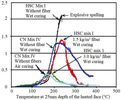
In his experiments, Phan (2002) observed that an alternative to minimize the effects of internal pressure formation on concrete can be conceived by introducing polypropylene fibers into concrete mixtures, and this fact has been proven in extensive research involving high strength concrete specimens. It was possible to characterize the behavior of the high strength concrete with respect to the internal pressure formation aspects, being considered equivalent to the normal strength concrete, when at high temperatures, simply by the introduction of polypropylene fibers.
This fact was verified by studying the pore pressure exerted on these two types of concrete (normal and high strength), coming from the high temperatures that can be reached in a fire, as shown in Figure 11 (Phan, 2002).
However, Phan (2002) pointed out that there are significant inconsistencies when associated only with pore pressure formation with the explosive spalling phenomenon, mainly because there are other fundamental factors that may influence the experimental programs in general. Only the introduction of polypropylene fibers does not necessarily guarantee the integrity of the concrete at high temperatures, and there may be other influencing agents, such as the type and size of the sample itself (specimens or structural elements).
2.5.1.1 The effect of reinforcement (reinforced concrete)
The experimental studies conducted by Professor Ph.D. Venkatesh Kodur7, while still linked to the NRC-CNRC National Research Council Canada, had a significant impact on research and development, especially regarding high strength concrete in fire conditions.
Kodur et al. (2000) tested columns, under load, of normal and high strength concrete with 305mm x 305mm cross section and 3810mm height. The normal concrete columns had 34MPa strength and the high strength ones 83MPa, both at 28 days of age.
In an extensive experimental program, Kodur et al. (2000) highlighted some innovative guidelines involving structural elements, submitted to fire resistance tests, which contributed considerably to a better performance of high strength concrete in fire situation. The main guidelines were based on procedures adopted for column confinement, as discussed below.
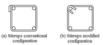
The main recommendation concerns the arrangement (configuration) of the transverse reinforcement (stirrups) with a hook-shaped locking (confinement) at 135° at the edge of the element and the corresponding reduction in stirrup spacing, which is approximately 0.75 times the usual required for normal concrete. The modifications proposed by Kodur et al. (2000) and also summarized in Kodur (2005) can be seen in Figure 12.
 |
||||
| Figure 12 Hight strength concrete column stirrups conventional configuration (a) and modified configuration (b) (Kodur, 2005). | ||||
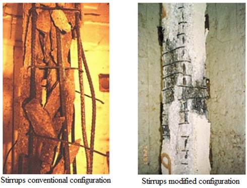
The positive result of Kodur's (2005) proposal is evident when looking at the two high-strength concrete elements of Figure 13, after the respective fire resistance verification experiments performed under the same test and material conditions. It is also important to note that in these samples there was no addition of polypropylene fibers in the concrete mix, only the modification in the arrangement (configuration) of the reinforcement (indicated in Figure 12).
 |
||||
| Figure 13 Results obtained after test under the high temperatures: (a) conventional configuration of the high strength column reinforcement and (b) modified configuration (Kodur, 2005). | ||||
In short, according to Kodur (2005), high strength concrete may actually be more susceptible to spalling when compared to normal strength concrete (fact recurrent for compressive strengths above 70 MPa). However, this phenomenon can be substantially minimized when some guidelines are adopted. As noted by Kodur et al. (2000), the moisture content of the concrete, the aggregate type and the cross-sectional size of the element are also relevant, besides the previous proposal of modification in the transverse reinforcement. They also point out that, in practice, the higher the moisture content of the concrete mix, the more intense and severe the spalling phenomenon.
2.5.1.2 Age effect
Morita et al. (2002) conducted extensive research to evaluate two parameters: (a) the influence of water/cement ratio on spalling intensity and (b) the influence of different reinforcement configurations of reinforced high strength concrete elements to minimize spalling effect, with and without the addition of polypropylene fibers in the concrete mix.
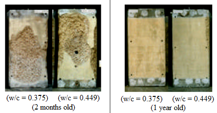
To evaluate the influence of water/cement ratio on spalling intensity, various types of concrete elements (with different w/c ratios) were tried, always at two different ages: two months old and one year old; without varying the dimensions of the structural element (70cm x 70cm x 140cm) and the thickness of the concrete cover (5cm). The fire simulation was performed according to the requirements of the ISO 834 curve over a predetermined period of 180 minutes (3h).
In Figure 14 it is possible to observe the considerable difference as a function of the age of the concrete element for equivalent water/cement ratio values (for example: w/c = 0.375 and w/c = 0.449).
The experiment conducted by Morita et al. (2002) seems to contribute to highlight how much the conducted research may be limited to evaluate spalling severity in concrete elements at premature ages, since the occurrence of this type of phenomenon depends significantly on the time factor (sample age).
Recently in Brazil (Britez, 2011), an experiment was carried out involving a large column, prototype of the high strength colored reinforced concrete columns of the e-Tower building - world record in compressive strength at the time (Helene & Hartmann, 2003) - , with advanced age of eight years.
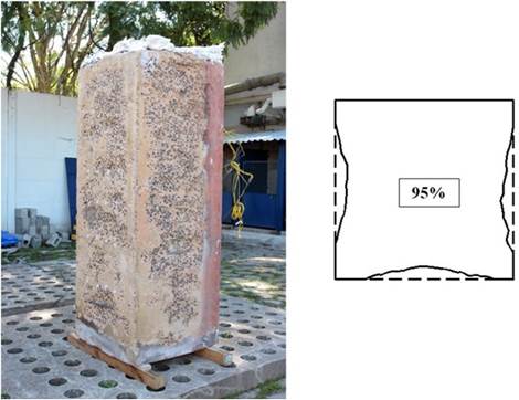
At the time, the results showed that the high strength concrete behaved in an upright manner (Figure 15) under fire, with 95% of its cross-sectional area maintained after the fire simulation test (only 5% effectively reduced by spalling). In addition, it was found in this experiment that the use of iron oxide-based pigment (colored concrete) also acted as an excellent colorimetric indicator (natural thermometer), helping to evaluate the post-fire structure.
The tested column (140 MPa f ck ) had a cross section of 70cm x 70cm, 2m high, 25mm average cover thickness; and was tested with three faces exposed to fire for a period of 180min (3h), without loading, with fire simulation characterized by the ISO 834 curve at the IPT Fire Safety Laboratory in São Paulo.
In addition to advanced age, Britez (2011) pointed out that other factors may have contributed positively to the good performance, such as the type of coarse aggregate used in the original concrete mix (basalt), as well as the cross-sectional size and reinforcement configuration.
 |
||||
| Figure 15 Column integrity and preserved cross-sectional detail after 180min (3h) test (showing the small cross-sectional reduction by spalling) (Britez, 2011). | ||||
2.5.1.3 The effect of load intensity
Although important and standardized, the tests carried out on specimens (cubic or cylindrical) and even on large structural elements (columns, beams and slabs), with loading increments and restrictions, are not yet enough for a real simulation of the behavior of concrete when inserted into a structural system, where other effects occur during a fire, such as nodes dilations/stretches, deformations and generalized displacements of all concrete elements exposed to fire.
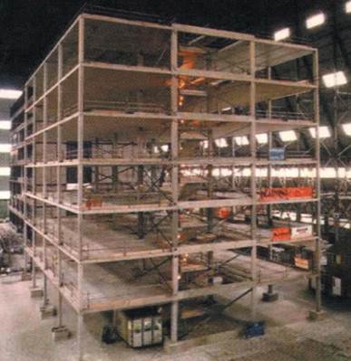
For obvious reasons associated with the costs involved and the complexity of carrying out these types of experiments, it is not common practice to simulate thermal experimental programs in a prototype building for structural element evaluation. However, such a widely publicized essay at the time was held in September 2001 at the Cardington Large Building Test Facility (LBTF)8. The prototype building of the Cardington project had seven floors, a total height of 25.2m and occupied an area of 675m² distributed in 7.5m x 7.5m square compartments, which in plan formed a rectangle with four compartments in one direction and three in another. A perspective of the Cardington project prototype building can be seen in Figure 16.
 |
||||
| Figure 16 Perspective of the reinforced concrete prototype structure designed for the Cardington fire simulation experiment (Chana & Price, 2003). | ||||
The prototype building had no beams and was characterized by a construction system consisting of columns and flat and massive slabs, which were 25cm thick, the internal columns 40cm x 40cm square cross section and the end columns 40cm x 25cm. The columns had a 40mm concrete cover thickness and were designed using high strength concrete (f ck = 103MPa at 28 days age), containing limestone aggregates, silica and 2kg of polypropylene fiber per cubic meter of concrete.
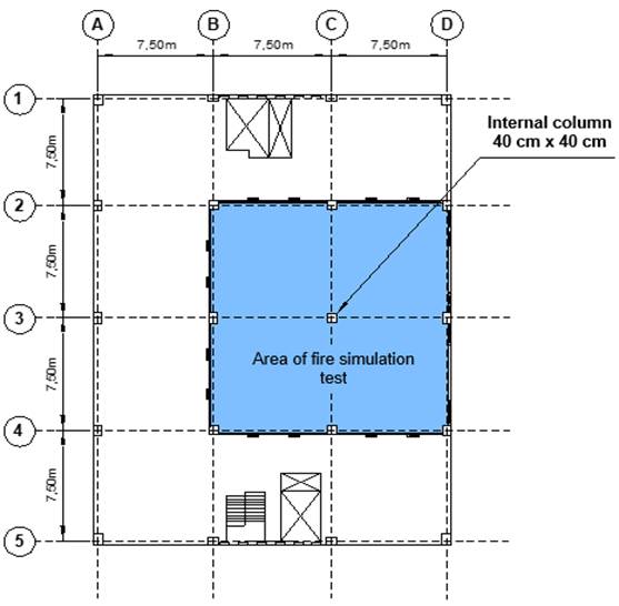
As described by Chana & Price (2003), the fire simulation took place in a region occupied by four compartments in a total area of 225m² with a height of 4.25m (ceiling height) on the ground floor of the building. Intentionally, an internal column was exposed on all four faces and some of its end partially, as observed in the plan of Figure 17. The experiment also involved ventilation openings projected on the outer walls of the compartments to be ignited, as well as the loading simulation. The slabs were evenly loaded with sandbags for a load of 3.25kN/m² (325kgf/m²) and in the column region additional bags were positioned to simulate an axial stress of 925kN (92.5tf).
 |
||||
| Figure 17 Plan of the prototype structure in reinforced concrete indicating the area under fire simulation (Chana & Price, 2003). | ||||
The fire was simulated by the burning of flammable material consisting of wooden pallets, positioned in the compartments to produce a thermal load of 40kg/m² (720MJ/m²), compatible with a typical commercial office fire load, for example.
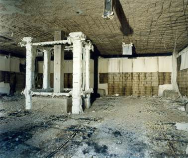
During the fire simulation, in the first 10 minutes of the experiment, there was the occurrence of low intensity, superficial spalling characterized by a discreet popping sound. However, after this period and for a further 15 minutes, the intensity was much higher, indicating a probable explosive spalling, which was later found mainly on the slab (ceiling) of the burning compartments (f ck = 74 MPa). After 25 minutes, spalling occurrences decreased significantly. The extent and severity of the occurrence of the spalling phenomenon after the experiment can be observed in Figure 18.
Regarding the integrity aspect of the high strength concrete, Chana & Price (2003) observed that the columns (f ck = 103MPa at the test) behaved satisfactorily, with low intensity spalling, negligible from the safety and structural stability point of view, even considering the effects of loading, bonding, among other normal attributes of a concrete structure in service state. They also added that, in this specific case, there may also have been a positive contribution of the addition of polypropylene fibers in the concrete mix (in the columns).
The researchers also concluded that the structural integrity of the slabs (f ck = 74MPa) was maintained despite widespread spalling and deflections of up to 7.8cm, which did not compromise safety because, as noted, no slabs collapsed and all continued to support the loads. distributed of 325kgf/m². In this context, it is noteworthy that in the case of solid slabs no polypropylene fibers were introduced in the concrete mix.
3. Conclusions
- It is considered that the text, in general, potentially contributes to demystify some beliefs and doubts about the phenomenon of spalling, one of the main circumstances of the material at high temperatures.
- Within the focus of fire characterized by cellulose based materials, even high intensity, it can generally be concluded that a reinforced concrete structure behaves better than that observed in small specimens as well as larger structural elements behave better than small structural elements, as well as structural elements in dry environments and with advanced age resists better to fire than newly built and wet ones.
- Although the scenario of a burnt-out concrete structure is very bleak and makes strong negative impressions, in light of engineering, the problem may be more aesthetic than structural. However, of course, the structure must be inspected by a qualified specialist, based on technical and experimental resources to properly characterize the residual properties of the reinforced concrete structure.
- It is difficult to imagine, in principle, the decision to demolish (may occur more due to social commotion or lack of property insurance) a reinforced concrete structure that has been subjected to high temperatures from a fire scenario. Corrective interventions for repairs and structural rehabilitation are much more common and recurrent, provided they are backed by detailed technical expertise, consent of related public agencies and interest of the building owner.
Referencias
Abrams, M. S. (1971), “Compressive strength of concrete at temperatures to 1600F”. American Concrete Institute, Special Publication, V 25, p.33-58.
American Concrete Institute (2008), ACI 318-08: building code requirements for reinforced concrete. Farmington Hills: ACI.
American Concrete Institute (1989), ACI 216R-89: guide for determining the fire endurance of concrete elements. Farmington Hills: ACI.
American Society for Testing and Materials (2007), E 119-07: standard test methods for fire of building construction and materials. West Conshohocken: ASTM.
Associação Brasileira de Normas Técnicas (1997), NBR 13860: glossário de termos relacionados com a segurança contra incêndio. Rio de Janeiro: ABNT.
Associação Brasileira de Normas Técnicas (2001), NBR 14432: exigência de resistência ao fogo de elementos construtivos de edificações - Procedimento. Rio de Janeiro: ABNT .
Associação Brasileira de Normas Técnicas (2001), NBR 5628: componentes construtivos estruturais: determinação da resistência ao fogo. Rio de Janeiro: ABNT .
Britez, C. A. (2011), “Avaliação de pilares de concreto armado colorido de alta resistência, submetidos a elevadas temperaturas”. Tese (Doutorado em Engenharia), Escola Politécnica, Universidade de São Paulo, São Paulo: USP, 252 f.
Cabrita Neves, I.; Rodrigues, J. P. C.; Loureiro, A. P. (1996), “Mechanical properties of reinforcing and prestressing steels after heating”. Journal of Materials in Civil Engineering, 8 (4), p.189-194, https://doi.org/10.1061/(ASCE)0899-1561(1996)8:4(189)
Chana, P.; Price, B. (2003), “The Cardington fire test”. Concrete, 37 (1), p. 28-33, Jan.
Costa, C. N. (2008), “Dimensionamento de elementos de concreto armado em situação de incêndio”. Tese (Doutorado em Engenharia), Escola Politécnica, Universidade de São Paulo, São Paulo: USP, 405 f.
Costa, C. N.; Silva, V. P. (2003), “Dimensionamento de estruturas de concreto armado em situação de incêndio: métodos tabulares apresentados em normas internacionais”. In: V Simpósio EPUSP sobre Estruturas de Concreto, 5, 2003, São Paulo.
Costa, C. N.; Silva, V. P. (2006), “Revisão histórica das curvas padronizadas de incêndio”. In: Seminário Internacional NUTAU: Tecnologia de Durabilidade, São Paulo: NUTAU-USP.
Costa, C. N.; Silva, V. P. (2004), “Considerações sobre a segurança das estruturas de concreto em situação de incêndio”. In: Seminário Internacional NUTAU: Demandas Sociais, Inovações Tecnológicas e a Cidade, 2004, São Paulo: NUTAU-USP . Disponível em: http://www.lmc.ep.usp.br/people/valdir/fire_safety/Nutau2004_concreto.pdf. Acesso em: nov. 2007.
Costa, C. N.; Figueiredo, A. D.; Silva, V. P. (2002), “Aspectos tecnológicos dos materiais de concreto em altas temperaturas”. In: Seminário Internacional NUTAU 2002. Sustentabilidade, Arquitetura e Desenho Urbano. São Paulo: NUTAU/FUPAM/FAUUSP.
European Committee for Standardization (2003), Eurocode 2: design of concrete structures: part 1-2: general rules: structural fire design. prEN 1992-1-2. Brussels, Belgium, 106 p.
Farny, J. A.; Panarese, W. C. (1994). “High-strength concrete”. Skokie, Ill.: Portland Cement Association, 53 p.
(fib) Fédération Internationale Du Béton (2007), “Fire design of concrete structures - materials, structures and modeling - State-of-art report”. Lausanne, fib. 97 p. (Bulletin d’information, 38).
Helene, P.; Hartmann, C. T. (2003), “HPCC in Brazilian office tower”. Concrete International, v. 25, n. 12, p. 64-68, Dec. 2003.
Holmes, M.; et al. (1982), “The effects of elevated temperatures on the strength properties of reinforcing and prestressing steels”. Structural Engineer, v. 60B, p. 7-13.
Jacobs, J. -P. (2007), “Comprehensive fire protection and safety with concrete”. Brussels: European Concrete Platform. 30p. Disponível em: http://www.britishprecast.org/publications/documents/06-Fire_brochure-3004071.pdf. Acesso em: 22 Jun. 2011.
Kalifa, P.; Menneteau, F.-D.; Quenard, D. (2000), “Spalling and Pore Pressure in HPC at High Temperatures”. Cement and Concrete Research, 30 (12), https://doi.org/10.1016/S0008-8846(00)00384-7
Khoury, G. A.; Anderberg, Y. (2000), “Concrete spalling review”. [S.l.]: FSD, 2000. 60 p. Report submitted to the Swedish National Road Administration.
Kodur, V. K. R.; et al. (2000), “Experimental studies on the fire endurance of high-strength concrete columns”. Canada: IRC/NRC, 146p. (NCR-CNRC Intemal Report 819).
Kodur, V. K. R.; et al. (2005), “Guidelines for fire resistance design of high-strength concrete columns”. Ottawa, Ontário, Canadá: IRC/NRC. (Report NRCC-47729). Disponível em: <http://irc.nrc-cnrc.gc.ca/pubs/fulltext/nrcc47729/>. Acesso em: nov. 2007.
Leonardo Da Vinci Pilot Project CZ/02/B/F/PP-134007 (2005), “Handbook 5: design of buildings for the fire situation”. Luxembourg: European Commission. Implementation of Eurocodes.
Morita, T.; et al. (2002), “An estimation method for fire resistance of reinforced concrete elements considering spalling”. Proceedings of the 1st Fib Congress. p. 119-128.
Neville, A. M. (1981), “Properties of concrete”. 3rd ed. London; Marshfield, Mass.: Pitman. 779 p.
Ongah, R.; Mendis, P. A.; Sanjayan, J. G. (2002), “Fire performance of high strength reinforced concrete walls”. In: Proceedings of the Australasian Conference On The Mechanics Of Structures And Materials, 17, Gold Coast, Austrália. Lisse: Balkema, p. 199-204. Disponível em: http://www.civenv.unimelb.edu.au/aptes/publications/Fire-HSC_walls.pdf. Acesso em: nov. 2007.
Phan, L. T. (2007), “High-strength concrete at high temperature: an overview”. In: Building and fire research laboratory. Gaithersburg: National Institute of Standard and Technology, Disponível em: http://www.fire.nist.gov/bfrlpubs/build02/PDF/b02171.pdf. Acesso em: nov. 2007.
Phan, L. T. (1996), “Fire performance of high-strength concrete: a report of the state-of-the-art”. In: Building and fire research laboratory. Gaithersburg: National Institute of Standard and Technology , NISTIR 5934. Disponível: http://www.fire.nist.gov/bfrlpubs/build96/art075.html. Acesso em: nov. 2007.
Purkiss, J. A. (1996), “Fire safety engineering design of structures”. Oxford: Butterworth-Heinemann, 369 p.
Seito, A I.; et al. (2008), “A segurança contra incêndio no Brasil”. São Paulo: Projeto. 496 p.
Taylor, H. F. W. (1990), “Cement chemistry”. London: Academic Press, 475 p.
The Concrete Centre (2004), “Concrete and fire: using concrete to achieve safe, efficient buildings and structures”. Camberley, Surrey, England. Disponível em: http://www.mace.manchester.ac.uk/project/research/structures/strucfire/DataBase/References/Concrete%20&%20Fire%203557%20lo%20res.pdf. Acesso em: nov. 2007.
Notes
1 Halon (halogenated hydrocarbon) is an extinguishing agent for chemical compounds formed by halogen elements (fluorine, chlorine, bromine and iodine). It was banned by the Montreal Protocol for being harmful to the ozone layer. The Montreal Protocol, in turn, is an international treaty in which the signatory countries undertake to replace ozone-depleting substances.
2 It is understood in this text that concretes considered “normal” (or conventional) are those with compressive strength below 50MPa, as recommended by the Portland Cement Association (PCA), recorded in High Strength Concrete (published in 1994 by Farny and Panarese) and adopted in this text.
3 From the verb to ignite (to ignite, to burn, to turn into fire).
4 Flashover can be defined as: instant of generalized inflammation, although there is no consensus in Brazilian literature about this translation. The use of the English term flashover is popular in Brazil and abroad.
5 The terms in the six categories proposed by fib (2007) were interpreted and translated by the authors of this article.
6 Some terms of the original table proposed by fib (2007) were interpreted and translated by the authors of this article.
7 Professor Ph.D. Venkatesh Kodur is currently linked to the Center for Structural Fire Safety and Diagnostics of the Michigan State University Department of Civil & Environmental Engineering.
8 The Cardington Large Building Test Facility (LBTF) was located within the BRE's (Building Research Establishment) Cardington Laboratory in Cardington, Bedford, approximately 70 km north of London, England. The laboratory was an area formed by an extensive hangar, which allows testing at a useful height of up to 50m in a wind-protected environment (Chana & Price, 2003).