| Applied Research | https://doi.org/10.21041/ra.v10i1.415 |
Numerical-experimental analysis of ceramic block masonry walls of different thickness at high temperatures
Análise numérico-experimental de paredes de alvenaria de bloco cerâmico com diferentes espessuras em altas temperaturas
Análisis numérico-experimental de paredes de mampostería con bloques de cerámica de diferentes espesores en altas temperaturas
F.
Bolina1
![]() , B. Tutikian1
*
, B. Tutikian1
*
![]() ,
J.
Gonçalves1
,
J.
Gonçalves1
![]() ,
T.
Souza1
,
T.
Souza1
![]() ,
G.
Manica1
,
G.
Manica1
![]()
1 Universidade do Vale do Rio dos Sinos, São Leopoldo, Brasil.
* Contact author: btutikian@terra.com.br
Reception:
May
01,
2019.
Acceptance:
November
11,
2019.
Published: 30 December 2019.
| Cite as: Bolina, F., Tutikian, B., Gonçalves, J., Souza, T. Manica, G. (2020), "Numerical-experimental analysis of ceramic block masonry walls of different thickness at high temperatures", Revista ALCONPAT, 10(1), pp. 22 – 35, DOI: http://dx.doi.org/10.21041/ra.v10i1.417 |
ABSTRACT
The study discusses the fire resistance of vertical sealing systems composed of ceramic bricks with vertical holes at high temperatures. The masonry sealing construction system is widely used in the Brazilian construction market because it is a low cost and high productivity system compared to conventional elements. The results were obtained with finite element computational models, using the Ansys Mechanical software, calibrated by a real scale experimental test, determining the fire resistance time (FRT) for different block geometries. The computational analysis led to results that point to a limit in efficiency of the wall thickness increase in order to reach a high FRT in relation to the thermal insulation.
Keywords:
fire resistance time,
fire,
compartmentatio.
RESUMO
O estudo discute sobre a resistência ao fogo de sistemas de vedação vertical compostos por blocos cerâmicos com furos verticais em altas temperaturas. O sistema construtivo de vedação em alvenaria é amplamente utilizado no mercado da construção civil no Brasil por tratar-se de um sistema de baixo custo e alta produtividade em comparação aos elementos convencionais. Os resultados foram obtidos com modelos computacionais de elementos finitos, através do software Ansys Mechanical, calibrados por ensaio experimental em escala real, determinando-se o tempo de resistência ao fogo (TRF) para diferentes geometrias de blocos. As análises computacionais levaram a resultados que apontam um limite para eficiência do aumento de espessura de uma parede para se atingir TRF elevados em relação ao isolamento térmico.
Palavras-chave:
tempo de resistência ao fogo,
incêndio,
compartimentação.
RESUMEN
Este estudio discute la resistencia al fuego de sistemas de sellado vertical compuestos por bloques cerámicos con agujeros verticales en altas temperaturas. La albañilería es ampliamente utilizada en el mercado de la construcción civil por tratarse de un sistema de bajo costo y alta productividad en comparación con los elementos convencionales. Los resultados fueron obtenidos con modelos computacionales de elementos finitos a través del software Ansys Mechanical, calibrados por ensayo experimental de resistencia al fuego a escala real, determinándose el tiempo de resistencia al fuego (TRF) para diferentes geometrías de bloques. Los análisis computacionales llevaron a resultados que apuntan un límite para la eficiencia del aumento de espesor de una pared para alcanzar altos TRF en relación con el aislamiento térmico.
Palabras clave:
albañilería estructural,
incendio,
compartimentación.
1. Introduction
In 1974, the fire of the Joelma building, located in São Paulo, Brazil, highlighted the risk of fire due to the absence of horizontal and vertical compartmentation. Compartmentation of areas is a fire safety feature and its main purpose is to contain the action of fire in order to restrict the area and thus the development of the flames, as well as to protect the dwellers from the action of fire for a determined period. Masonry walls and partitions can promote compartmentation between rooms, mitigating the spread of fire and smoke between environments. (MARCATTI et al., 2008).
With the growing need to build with quality and safety, especially due to the Brazilian Standard of Performance of Housing Buildings, NBR 15575 (ABNT, 2013) taking effect, the need to verify the performance of building systems in terms of (a) sustainability, (b) habitability and (c) security gained strength. According to NBR 15575 (ABNT, 2013), among the systems that must meet these conditions, the vertical sealing system must follow minimum fire requirements. In addition, compartmentation requirements are demanded by state fire department regulations in Brazil, which reinforces this need and requires designers to meet these standards.
It is common to associate fire resistance of masonry elements with their thickness, but other factors must be considered, such as the amount of air layers contained in the blocks. There is a complex temperature distribution in the section of these elements that should be further investigated due to the different heat conduction mechanisms in them. Masonry also varies by region of manufacture, and by changing available constituent materials and local manufacturing processes. (ZSEMBERY, 2013).
For the project of masonry in fire situation, Eurocode 6 (EN 1996-1-2, 2005) allows two types of sizing methods. One uses fixed data, which provides the minimum required wall thickness dimension to obtain the fire resistance time. The second method, through calculation that considers the material failure modulus when exposed to high temperature, defines the element specifications according to temperature, slenderness rate and deformation due to restricted thermal expansion. (RIGÃO, 2012).
Considering that NBR 15220 (ABNT, 2003) uses the apparent thermal conduction simplification and presents a coefficient for the thermal conduction of the confined air much lower than that of ventilated air, it may be deduced that the reason for this reduction is due to convection and thermal radiation transport that occurs between the faces that generate this confinement. It may also be assumed that the explanation for the difference in apparent thermal conduction values in Bai’s (2017) tests is related to the fact that their samples with smaller alveoli have a larger number of cavities, resulting in more convection and thermal radiation phenomena occurring within the sample.
Laboratory tests are performed to understand the performance of vertical sealing systems in a fire situation and, consequently, make their use feasible. In Brazil, the standard that regulates the fire resistance tests of these systems is NBR 5628 (ABNT, 2001) for walls with structural function and NBR 10636 (ABNT, 1989) for walls without structural function. According to the standards, the tests must be performed in real scale, turning the process costly, which, added to the limited number of vertical furnaces in Latin America, makes the technical collection in this area limited. (RIGÃO, 2012).
Therefore, the development of theoretical models and computer simulations is necessary to evaluate the behavior of masonry in a fire situation. In these analyses, heat transmission and mechanical behavior are factors that occur in a three-dimensional plane. However, most existing models are based on two-dimensional approaches, based on a macroscopic scale, preventing proper analysis of convective and radiative heat transmission within the ceramic blocks. (NGUYEN et al., 2009).
Aiming to make computational analysis more representative, computational models should be calibrated with data obtained through experimental tests. The available results on vertical sealing system tests approach the items of tightness (T), thermal insulation (I) and mechanical resistance (R), which makes it difficult to perform an advanced computational model, which requires a few other relevant information. (NGUYEN; MEFTAH, 2012).
Therefore, this work evaluated the influence of ceramic block geometry with vertical holes on the fire resistance of vertical sealing systems in fire situations, using computer assisted models, calibrating them through results of fire resistance tests in real scale experimental walls, elaborated according to NBR 5628 (ABNT, 2001). The study was divided into five stages: (1) introduction; (2) experimental program; (3) numerical analysis; (4) results and discussion; and (5) conclusion.
2. Experimental program
2.1 Wall prototype construction
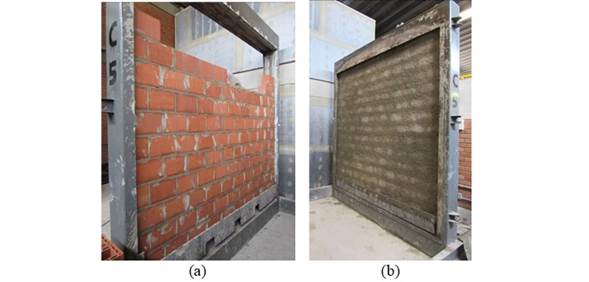
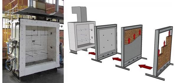
The wall used as a calibration object was named P1. This system has dimensions consisting of 3,15 x 2,80m and was built in a metal gantry in laboratory, as shown in Figure 1.
 |
||||
| Figure 1. Constructive sequence of wall P1. | ||||
For the execution of the experimental test wall, ceramic blocks with fbk 8 MPa were used, containing vertical holes and dimensions of 14 x 19 x 29 cm, and also with laying mortar joint of cement, sand and lime, with 4 MPa of medium compressive strength, in addition to aerator additives, hydration stabilizer and water retainer.
2.2 Instrumentation
To evaluate the wall temperature throughout the test, five thermocouples were used in the face exposed to the fire and five thermocouples in the unexposed face, placed in its surface, as shown in Figure 2. Also, five thermocouples were added along the block section, as shown in Figure 3.
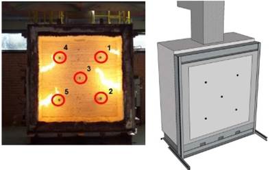
Figure 2.
External thermocouples.
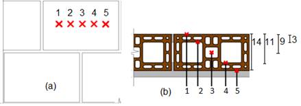
Figure 3.
Location of internal thermocouples on blocks in (a) section and (b) plan.
2.3 Vertical furnace
The test was performed at Unisinos’ Fire Safety Laboratory. The wall was tested after 56 days of curing in a vertical furnace. The furnace has four burners arranged according to Figure 4, controlled by two thermocouples that allow the measurement of temperature evolution by ISO 834 (2014). Figure 4 also shows the wall mounting and installation sequence in the test furnace. The furnace has a chimney that regulates the flow of gases generated by the heating and the internal pressure throughout the test, as well as thermal insulation composed by ceramic fiber blanket and four gas burners, digitally controlled by a digital control center.
 |
||||
| Figure 4. Detail of system coupling to vertical furnace. | ||||
3. Numerical analysis
3.1 Analysis premises
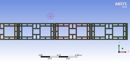
For the elaboration of the computational model, the Ansys Mechanical Transient Thermal program was used. In this program, a mesh of elements was generated, as shown in Figure 5. Each division displayed in the block section represents a finite element to be calculated, so that the program performs a series of smaller calculations and groups them to present the final result.
 |
||||
| Figure 5. Hypothetical computational mesh for computational analysis. | ||||
The finite elements generated by the program for the analysis were QUAD_4 type, which generates four nodes and represents close square shapes. The minimum and maximum size of each element was determined manually, being the smallest possible element with 1 mm side and the largest possible element with 50 mm side. The mortar was considered as an inert element, with complete iteration with the block. The thermal conductivity of the block was given as a function of the temperatures extracted from the experimental model. This simulation was made in 2 dimensions, with the sole purpose of considering the isotherms of the blocks under analysis.
With the calculation mesh, the temperature curve to which the wall should be exposed was inserted, following the curve given by ISO 834 (ISO, 2014). The initial temperature defined for the computational analysis was the same as that used in the experimental test, 20ºC.
3.2 Parameters obtained in experimental calibration
To perform the experimental analysis, it was necessary to use parameters related to the thermal properties of the materials involved, that is: density, specific heat and thermal conductivity coefficient. The parameters defined for the calibration are presented in Table 1.
| Table 1. Parameters defined for the calibration. | ||||||||||
| Parameter | Value | |||||||||
|---|---|---|---|---|---|---|---|---|---|---|
| Density (kg/m³) | Thermal conductivity (W.C/m) | Specific heat J.C/kg) | ||||||||
| Air | 1,125 | 0,025 | 1005 | |||||||
| Mortar | 1709 | 0,9 | 1550 | |||||||
| Block | 1200 | 2,5 | 880 | |||||||
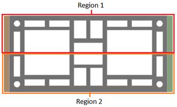
For the definition of the convection values, considering its variability with the increase in temperature, the block was divided into two regions, as shown in Figure 6, and for each one of them a thermal conductivity coefficient value was assigned according to the evolution of the test time, when temperatures rose. The coefficients used are shown in Table 2.
 |
||||
| Figure 6. Regions defined for convection coefficients. | ||||
Table 2.
Thermal convection coefficients. Block region
Test time
30 min
60 min
120 min
240 min
Region 1
30 (W.C/m)
14 (W.C/m)
9 (W.C/m)
4 (W.C/m)
Region 2
0,7 (W.C/m)
20 (W.C/m)
6 (W.C/m)
0,5 (W.C/m)
These values were extracted from the experimental model and inserted in the computational simulation.
3.3 Temperature reading points
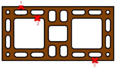
The temperature reading points in the block were the same as those experimentally defined, as shown in Figure 7. Thermocouples 3 and 4, which are not shown in Figure 7, were used to measure the results of air temperature in the computational modeling.
 |
||||
| Figure 7. Points considered in the blocks’ temperature measurement. | ||||
3.4 Calibration and validation of the computational model
For the validation of the computational model, through the experimental analysis in vertical furnace, the variables considered were the parameters of density, thermal conductivity, specific heat and thermal convection, which were extracted from the test. Through these reports, the computational model was calibrated with experimental data, as shown in Table 3.
| Table 3. Temperatures reached in the calibration model. | ||||||||||
| Points | Time | |||||||||
|---|---|---|---|---|---|---|---|---|---|---|
| 30 min | 60 min | 120 min | 240 min | |||||||
| At point 1 | 833 ºC | 945 ºC | 1047 ºC | 1151 ºC | ||||||
| At point 2 | 321 ºC | 608 ºC | 701 ºC | 846 ºC | ||||||
| At point 3 | 46 ºC | 95 ºC | 237 ºC | 417 ºC | ||||||
The validation of the model occurred through the values obtained in the numerical analysis with the experimental analysis.
3.5 Extrapolation of experimental results
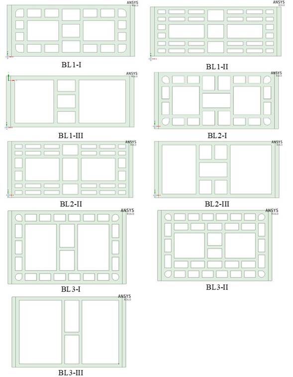
With the calibration performed according to the experimental result, the process of computational extrapolation for different block geometries began. For this, three commercial thicknesses of 11,5, 14 and 19 cm of ceramic blocks were used. For each of these thicknesses, three blocks were defined, varying the number of alveoli and, therefore, percentage of voids. Three distinct geometries were proposed, but the thickness of the internal walls of the block were constant, with 9 mm externally and 8 mm internally, as shown in Figure 8.
The 11,5 cm thick block family was called BL1; 14 cm thick BL2; and the 19 cm thick BL3. The percentage variations of voids within the same block family were calculated using the ratio between gross area and net area, and referred to as indexes I, II and III. Figure 9 details the blocks used in this study. The blocks were named sequentially BL1 to BL3. It is observed that the blocks with II index (BL1-II, BL2-II and BL3-II) are found in the market, the commercial ones. From there, it has been proposed blocks with smaller and slightly larger alveoli, those with I index (BL1-I, BL2-I and BL3-I), and blocks with larger alveoli and in small quantity, those with III index (BL1-III, BL2-III e BL3-III).
Table 4 shows the nomenclatures, measurements and void volume (%) calculated for each type of ceramic block.
3.6 Times of analysis of block isotherms
The isotherms of the blocks in the computational program were calculated at 30, 60, 90, 120, 180 and 240 minutes. To define the Fire Resistance Time (FRT) of each block, the limit temperature of 200ºC (180+20°C) on the unexposed face to the fire for an isolated thermocouple was defined with base on the precepts of NBR 10636 (ABNT, 1989).
4. Results and discussion
Due to the predominant criterion of FRT definition being the temperature of the unexposed face of the block, these measurements were used for the analysis, with the limit temperature of 200 °C on the unexposed face. Block isotherms were collected in the computational program at 30, 60, 90, 120, 180 and 240 minutes. Figure 10 presents the isotherms of some of the blocks used in this study and Figure 11 displays the comparison among all the blocks, with variation in geometry, percentage of voids and thicknesses.
According to Figure 11, it is possible to determine that the alveoli have a great influence on the thermal insulation of the blocks, especially at higher temperatures. It was observed that choosing a block with a larger number of alveoli may be a more effective option, rather than choosing a thicker block, when high FRT is desired, which corroborates with what was concluded by Lee (2017), as to the fact that the influence of the alveoli in a block becomes practically null at low temperatures. Considering the response of the models, it was found that, at higher temperatures, the convective and irradiative phenomena that occur inside the blocks are more relevant than the thermal conduction, which occurs through the material. This is stressed in NBR 15220 (ABNT, 2003), where it defines confined air as an excellent thermal insulator.
From the results of Figure 11, it was possible to extrapolate the void values required to meet a thermal insulation time (TIT) for each type of block, presented in Table 5. Extrapolation was made by only performing adjustments in the shape of the block, based on the one that had been calibrated by experimental means.
81,73%
For comparison purpose, temperature evolution curves of the unexposed face of the Index II blocks were generated, in order to compare the influence of the block’s thicknesses, presented in Figure 12.
From these curves it was possible to determine the thickness related to TIT desired in a sealing wall, shown in Table 6.
Table 6 presents minimum wall thicknesses that meet the requirements in Eurocode 6 (EN 1996-1-2, 2005), reinforcing the validation of the parameters used. Through observation of the data generated from the analysis of the influence of the block thickness, it is possible to verify that this factor has a good influence on lower TITs. However, after 90 minutes, this parameter tends to have a lower TIT increment rate.
5. Conclusions
In this work, the fire resistance of ceramic blocks used for structural masonry was analyzed through the finite element method using the Ansys Mechanical program. The blocks tested by the software were molded into an uncoated configuration and with 1 cm mortar joints, varying only the thickness and number of alveoli in each simulation.
The computational analyses led to results that point to a limit in the efficiency of the wall thickness increase to reach high FRTs in relation to the thermal insulation. It was also possible to demonstrate thermal insulation gain by increasing the number of alveoli within a block. Thus, it was possible to verify the importance of convection and thermal radiation processes in fire safety, which are more relevant than the thermal conduction of the assessed material.
When an analysis is performed only regarding the block thicknesses, the results converge towards what is presented in Eurocode 6 project table (EN 1996-1-2, 2005). When considering the number of alveoli, the potential gain in thermal resistance without varying the thickness of a block meets the concepts of thermal comfort that are presented in NBR 15220. This fact reinforces the relevance of using this concept in the elaboration of a Brazilian standard for projects of structural masonry in fire situation.
References
Associação Brasileira de Normas Técnicas (1989). ABNT NBR 10636: Paredes divisórias sem função estrutural - Determinação da resistência ao fogo - Método de ensaio. Rio de Janeiro.
Associação Brasileira de Normas Técnicas (2001). ABNT NBR 5628: Componentes construtivos estruturais - Determinação da resistência ao fogo. Rio de Janeiro.
Associação Brasileira de Normas Técnicas (2013). ABNT NBR 15575: edificações habitacionais: desempenho. Rio de Janeiro.
Associação Brasileira de Normas Técnicas (2003). ABNT NBR 15220: Desempenho térmico de edificações. Rio de Janeiro.
Bai, G. et al. (2017). Study on the Thermal Properties of Hollow Shale Blocks as Self-Insulating Wall Materials. Advances in Materials Science and Engineering. 2017(ID 9432145), p. 12.
Ehrenbring, H. Z., Quinino, U., Oliveira, L. S., Tutikian, B. F. (2019), Experimental method for investigating the impact of the addition of polymer fibers on drying shrinkage and cracking of concrete. Structural Concrete. 20(3), 1064-1075. DOI: https://doi.org/10.1002/suco.201800228.
European Commitee Standardization (2005). Eurocode 6: Design of masonry structures: Part 1-2: General rules - Structural fire design. Brussels.
Gil, A., Pacheco, F., Christ, R., Bolina, F. L., Khayat, K. H., Tutikian, B. F. (2017), Comparative study of concrete panels’ fire resistance. ACI Materials Journal. 114(5), 755-762.
International Organization for Standardization (2014). ISO 834-11: Fire resistance tests - Elements of building construction - Part 11: Specific requirements for the assessment of fire protection to structural steel elements. Switzerland.
Lee, L. S. H., Jim, C. Y. (2017). Subtropical summer thermal effects of wirerope climber green walls with different air-gap depths. Building and Environment, v. 126, p. 1-12. DOI: https://doi.org/10.1016/j.buildenv.2017.09.021
Marcatti, J., Coelho Filho, H. S., Berquó Filho, J. E. (2008), Compartimentação e afastamento entre edificações. In: SEITO, A. I. et al (Coord.). A segurança contra incêndio no Brasil. São Paulo: Projeto Editora. p. 496. ISBN:978-85-61295-00-4
Nguyen, T. D. et al. (2009), The behaviour of masonry walls subjected to fire: Modelling and parametrical studies in the case of hollow burnt-clay bricks. Fire Safety Journal. 44(4), p. 629-641. DOI: https://doi.org/10.1016/j.firesaf.2008.12.006
Nguyen, T. D., Meftah, F. (2012), Behavior of clay hollow-brick masonry walls during fire. Part 1: Experimental analysis. Fire Safety Journal. 52. p. 55-64. DOI: https://doi.org/10.1016/j.firesaf.2012.06.001
Pacheco, F., Souza, R., Christ, R., Rocha, C., Silva, L., Tutikian, B. F. (2018), Determination of volume and distribution of pores of concretes according to different exposure classes through 3D microtomography and mercury intrusion porosimetry. Structural Concrete. 19(2). p. 1419-1427. DOI: https://doi.org/10.1002/suco.201800075
Rigão, A. O. (2012), Comportamento de pequenas paredes de alvenaria estrutural frente a altas temperaturas. 142 f. Dissertação (Mestrado) - Curso de Engenharia Civil, Universidade Federal de Santa Maria, RS, Brasil.
Zsembery, S., Lawrence, S. (2013), Manual 2 - The Properties of Clay Masonry. Think Brick. Austrália.
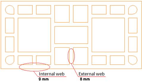
Figure 8.
Internal and external walls of the blocks.
Table 4. Blocks used in simulations.
Block name
Dimensions (cm)
Total voids (%)
BL1-I
11,5 x 19 x 26,5
54,24
BL1-II
11,5 x 19 x 26,5
43,72
BL1-III
11,5 x 19 x 26,5
71,42
BL2-I
14 x 19 x 26,5
54,2
BL2-II
14 x 19 x 26,5
58,6
BL2-III
14 x 19 x 26,5
72,82
BL3-I
19 x 19 x 26,5
64,36
BL3-II
19 x 19 x 26,5
57,39
BL3-III
19 x 19 x 26,5
79,03
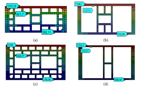
Figure 10.
Block isotherms of (a) BL2-I, (b) BL2-III, (c) BL3-II and (d) BL3-III at 180 minutes.
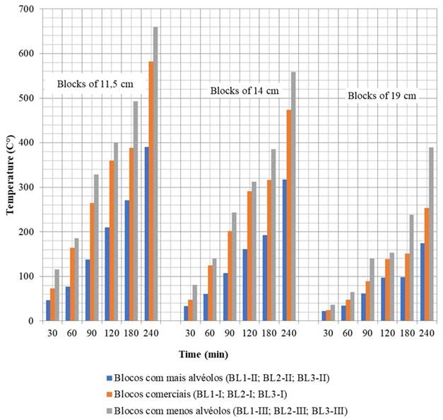
Figure 11.
Comparison among the temperatures on the unexposed faces of all tested blocks.
Table 5.
TIT determination from the percentage of voids in a block.
Block thickness
Maximum percentage of voids for FRT in minutes
30
60
90
120
180
240
11,5 cm
79,11%
86,64%
45,95%
42,17%
40,25%
30,95%
14 cm
80,71%
62,89%
58,30%
53,08%
45,96%
19 cm
84,90%
84,90%
84,90%
84,90%
74,02%
59,62%
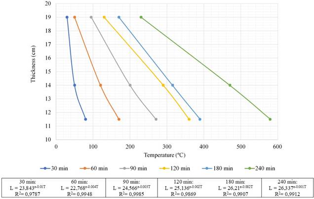
Figure 12.
Block curves of BL1-II, BL2-II and BL3-II
Table 6. TIT determination from block thickness.
Minimum thickness for FRT
FRT (min)
30
60
90
120
180
240
Thickness (cm)
11,5
11,5
14
19
19
-