
| Basic Research | https://doi.org/10.21041/ra.v10i3.395 |
Development and analysis of a numerical model of the reinforced concrete expansion due to uniform corrosion
Desenvolvimento e análise de um modelo numérico da expansão do concreto armado sujeito à corrosão uniforme
Desarrollo y análisis de un modelo numérico de expansión de concreto reforzado sujeto a corrosión uniforme
E. F.
Felix1
*
![]() ,
R.
Carrazedo1
,
R.
Carrazedo1
![]() ,
E.
Possan2
,
E.
Possan2
![]() ,
E. S.
Ramos1
,
E. S.
Ramos1
![]()
1 University of São Paulo at São Carlos School of Engineering, Brasil.
2 Universidade Federal da Integração Latino-Americana (UNILA), Brasil.
*Contact author: emerson.felipe.felix@gmail.com
Reception: February 21, 2019.
Acceptance: December 11, 2019.
Publication: September 01, 2020.
| Cite as: Felix, E. F., Carrazedo, R., Possan, E., Ramos, E. S. (2020), "Development and analysis of a numerical model of the reinforced concrete expansion due to uniform corrosion", Revista ALCONPAT, 10 (3), pp. 300 – 316, DOI: https://doi.org/10.21041/ra.v10i3.395 |
Abstract
This paper presents the modeling and analysis of the corrosion effects due to carbonation on reinforced concrete elements through a numerical model based on the Finite Element Method. In order to minimize corrosion damage, tools are required to understand the pathological manifestation on the mechanical behavior of reinforced concrete. It was found that depending on the reinforcement corrosion stage, the state of stress and deformation of the concrete element is compromised. Besides, results show the efficiency of the developed model and its applicability to the simulation of the mechanical behavior of reinforced concrete structures subjected to uniform corrosion.
Keywords:
reinforced concrete,
corrosion,
numerical modeling,
finite element method.
Resumo
Este trabalho apresenta a modelagem e análise dos efeitos da corrosão por carbonatação em elementos de concreto armado através de um modelo numérico baseado no Método dos Elementos Finitos. Para controlar e minimizar os danos associados à corrosão faz-se necessário deter ferramentas e conhecimento suficientes para entender os efeitos desta manifestação patológica sobre o comportamento mecânico do concreto armado. Diante dos resultados obtidos, constatou-se que a depender do nível de corrosão das armaduras, o elemento de concreto tem seu estado de tensão e deformação comprometido. Ademais, os resultados apontam a eficiência do modelo desenvolvido e a sua aplicabilidade frente à simulação do comportamento mecânico de estruturas de concreto armado sujeitas à corrosão uniforme.
Palavras-chave:
concreto armado,
corrosão,
modelagem numérica,
método dos elementos finitos.
Resumen
Este trabajo presenta la modelización y análisis de los efectos de la corrosión por carbonatación en elementos de concreto reforzado a través de un modelo numérico basado en el Método de los Elementos Finitos. Para controlar y minimizar el daño asociado a la corrosión se hace necesario disponer de herramientas y conocimientos suficientes para comprender los efectos de esta manifestación patológica sobre el comportamiento mecánico del concreto reforzado. Ante los resultados obtenidos, se constató que, dependiendo del nivel de corrosión de las armaduras, el elemento de concreto tiene su estado de tensión y deformación alterado. Además, los resultados indican la eficiencia del modelo desarrollado y su aplicabilidad frente a la simulación del comportamiento mecánico del concreto reforzado con corrosión uniforme.
Palabras clave:
concreto reforzado,
corrosión,
modelización numérica,
método de los elementos finitos.
1. Introduction
The degradation of reinforced concrete structures due to the reinforcement corrosion is difficult to measure owned to the complexity of the physicochemical phenomenon and the multiple parameters involved (Mehta and Monteiro, 2014). From the mechanics of materials and structures point of view, the main effect of corrosion on reinforcement is loss of steel mass and, consequently, transformation of steel into corrosion products, or rust, as is commonly known. The volume of corrosion products is greater than steel, generating tensile stresses that leads to cracking and spalling concrete over time.
In general, concrete provide conditions to protect the reinforcement against corrosion, owning to the high alkalinity of the pore solution of concrete (pH between 12 and 13). However, this protection is lost as concrete is subjected to the different aggressive agents present in the atmosphere, i.e. chloride (Cl-) and carbon dioxide (CO2) ions (Gentil, 2011).
Depending on the concentration of the aggressive agent present in the atmosphere, the corrosive process can be classified as uniform or localized. Localized or pitting corrosion occurs when chloride ions cause an increase in the electrical conductivity of the concrete and attack the passivating layer that protects the reinforcement. In this case, corrosion is highly localized by pitting resulting in relatively minor mass loss, justifying the term "localized" used in its classification (Ribeiro et al., 2015).
The corrosive process is said to be uniform or by carbonation when the CO2 content present in the atmosphere is predominant to that of chloride ions. Diffusion of CO2 decreases the pH of the cement matrix (from approximately 13 or 12 to 9), which eliminates the passivation layer that surrounds the reinforcement, making it prone to corrosion (Mehta and Monteiro, 2014).
Usually, uniform corrosion is seen in low-quality concrete structures, where the concrete cover is insufficient to ensure protection, or in severe aggressive environments (Ribeiro et al., 2015). In these cases, corrosion leads to the formation of rust at the interface of steel and concrete, and these products occupy 3 to 10 more volume than initially (Helene,1986).
According to Andrade et al. (1993) and Ribeiro et al. (2015), the formation and development of corrosion products due to uniform corrosion depend on several environmental factors (ambient temperature, relative humidity, degree of environmental aggressiveness, CO2, exposure content, among others), or on constructive factors (type of cement, water / cement ratio, type of steel, concrete cover, among others).
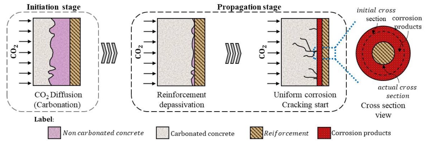
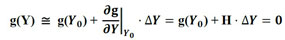
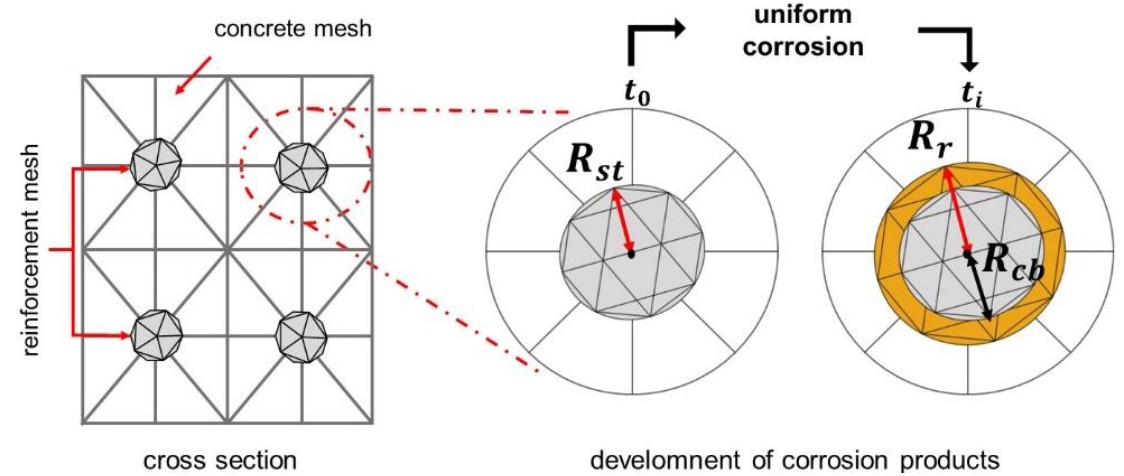
With the formation of corrosion products, internal stresses are developed at the interface between steel and concrete. As stresses increase, surpassing concrete tensile strength, micro cracks appear in the concrete matrix which increases in size and thickness as the pathological manifestation progress, spreading throughout the structural element until it spalls the concrete cover, affecting the durability and reducing the service life of the structure. The degradation process is presented in Figure 1.
 |
||||
| Figure 1. Corrosion development in concrete | ||||
In order to minimize the effects of corrosion it is necessary to understand the initiation and propagation stages of the corrosive process, enabling the reduction of its incidence and, in advanced cases, the repair and / or restoration of the structures in order to increase their useful life, and reducing risks to its users.
Several experimental assessments have been carried out for the study of corrosion and its effects on the mechanical behavior of reinforced concrete, such as Molina et al. (1993), Almusallam (2001), Graeff (2007) and Zhu (2014), which resulted in relevant findings in the subject. However, three important limitations are pointed out by the researchers: (i) the difficulty of studying separately the different factors that influence the corrosion process; (ii) high costs and (iii) time required for experimental testing.
Several numerical tools were developed with the advancement in technology, for example, the Boundary Element Method (BEM), the Finite Element Method (FEM), Artificial Neural Networks (ANN), among others, leading to creative ways to solve some numerical problems, since these tools may help out to overcome those limits.
Hansen and Saouma (1999), Maruya et al. (2003) and Bhargava et al. (2005) used several numerical tools for an automated resolution of mathematical equations related to the corrosion mechanisms and to analyze the effects of corrosion and its propagation process.
Similar procedures were adopted by Isgor and Razaqpur (2006), Xu et al. (2009), Du and Jin (2014), Ožbolt et al. (2014) and Paul and Zijl (2016), solving the corrosion chemical and mechanical problem in reinforced concrete structures by FEM.
Thus, the present work proposes a numerical model developed with the Positional Finite Element Method (Positional FEM) for the study of corrosion and its effects. The proposed model enables the simulation of reinforced concrete expansion due to uniform corrosion and, in particular, the formation of corrosion products.
2. Concrete expansion model due to corrosion
2.1 Mechanical model
In order to simulate the expansion of reinforced concrete structures due to uniform corrosion, especially the formation of corrosion products, a numerical tool based on the Positional Finite Element Method was developed. The Fortran code combines a few analytical formulations to evaluate representative corrosion parameters. The mechanical behavior of the reinforced concrete is evaluated by a formulation based on the Positional Finite Element Method for composite solids, initially developed by Vanalli et at. (2008) and recently extended by Paccola e Coda (2016), in which the nodal parameters are the positions, and the deformations are related to the initial position of the body. Green strain measure and Saint-Venant-Kirchhoff constitutive law are employed.
 |
||||
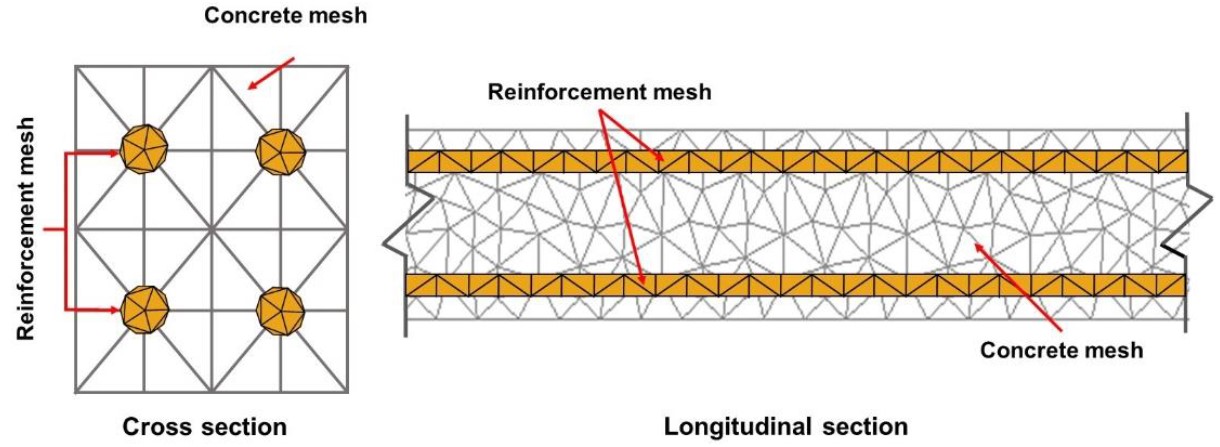
| Figure 2. Example of discretization of a reinforced concrete beam cross and longitudinal sections. | ||||
Reinforced concrete is discretized considering the concrete and reinforcement matrix (Figure 2). Both the concrete matrix and the reinforcements are represented by means of flat triangular two-dimensional elements, the reinforcement mesh being coupled to the concrete matrix by means of the drawing technique, described in Vanalli et al. (2008) and Paccola and Coda (2016). In this case, a perfect adhesion between the particle and the matrix occurs, making the use of particle elements do not increase the degrees of freedom of the system. All the degrees of freedom of the particle elements are written based on the elements of the matrix.
In the sequence, the process used in this work to obtain the mechanical response of a problem via MEFP for reinforced concrete is briefly presented.
Considering conservative forces and the principle of the minimum stationary potential energy for the solution of the geometric nonlinear problem, the total potential energy of a particulate compound solid is described in equation (1).
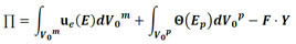 |
(1) |
in which Θ is the specific strain energy of the particle elements, ue is the specific strain energy of the matrix elements, F is the vector of conservative external forces, Y is the vector of nodal positions, Ep is the Green-Lagrange strain related to the particle elements, E is the Green-Lagrange strain related to the matrix elements, both evaluated by Equation (2), and V0p e V0m are the initial particle and matrix volumes, respectively.
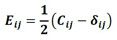 |
(2) |
where Eij is the elastic Green-Lagrange strain, Cij is the Cauchy-Green stretch tensor, and δij is the Kronecker delta.
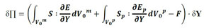
As the variation of the total potential energy is zero in the equilibrium, the problem is resumed to find the current nodal position vector, as presented in Equation (3).
 |
(3) |
in which S is the second Piola-Kirchhoff stress developed in the elastic matrix, and Sp is is the second Piola-Kirchhoff stress developed in the particle elements. Since the problem is nonlinear, solution of Equation (3) is obtained by the Newton-Raphson process, over the unbalanced or residue vector g , as shown in Equation (4).
 |
(4) |
where Fmint is the internal force portion of the matrix elements and Fpint is the internal force portion of the particle elements. Equation (4) is expanded by a Taylor series, as described in Equation (5).
 |
(5) |
in which Y is current trial position, and H is the Hessian matrix. H is decomposed into two matrices, one referred to the stiffness of the matrix elements (Hm), and another referred to the stiffness of the particle elements (Hp), as described in Equation (6).
 |
(6) |
The nonlinear system solution presented in Equation (5) by the Newton-Raphson method provides the correction of the trial position (Y = Y0+ ∆Y). Correction to trial position is applied until a convergence criterion such as |∆Y|/|X| is achieved. Notice that X is the vector of the nodal positions of the initial configuration.
For further details, the reader is invited to consult in Paccola and Coda (2016) and Coda (2018).
2.2 Corrosion modeling
Understanding how corrosion products are developed and distributed around the reinforcement enables the development of models and tools that can describe the strains and stresses that arise from corrosion progress. These models assist in studies concerning the effects of corrosion on the mechanical behavior of concrete, durability and useful life of these structures.
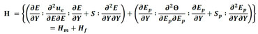
Over the past few years, some models have been proposed to describe the distribution of rust around the reinforcement, i.e., Liu and Weyers (1998), Yuan and Ji (2009), Balafas and Burgoyne (2010) and Kiani and Shodja (2011). These models are divided into linear and non-linear, as shown in Figure 3.
 |
||||
| Figure 3. Rust formation profile: (a) linear e (b) non linear. | ||||
Thus, considering that the carbonation induced corrosion develops uniformly throughout the reinforcement, the model by Kiani and Shodja (2011) is used in this work to represent the corrosion progress.
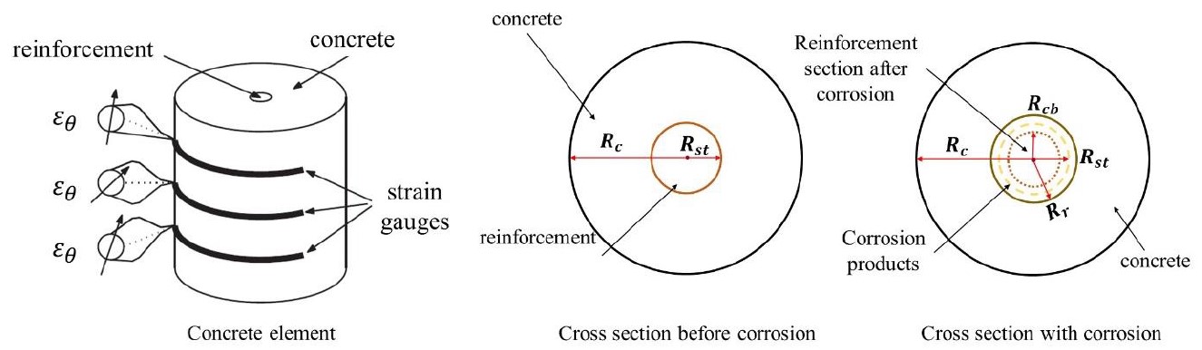
Kiani and Shodja (2011) developed a linear model for the formation of rust in reinforced concrete structures, fitting experimental data from cylindrical reinforced concrete specimens of known diameter and physical properties (see Figure 4).
 |
||||
| Figure 4. Model schematics of Kiani and Shodja (2011). | ||||
The model by Kiani and Shodja (2011) requires the evaluation of the reduced radius of the reinforcement due to corrosion ( Rcb ) and the radius of the rust front ( Rr ), which can be obtained in (7) and (8) respectively. It is also required to calculate the volume of the produced rust, according to (9), and the volume of consumed steel, according to (10).
 |
(7) |
 |
(8) |
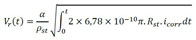 |
(9) |
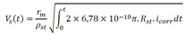 |
(10) |
where Rst is the initial radius of the reinforcement (in m), α is the ratio of steel density of steel to the corrosion products density, ρst the steel density (in kg/m³), rm the ratio of iron mass to the molecular mass of corrosion products, t (in s) is the time parameter, measured from the instant the reinforcement is depassivated and icorr the natural corrosion current density (in A/m²), given by (11).
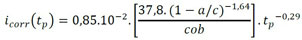 |
(11) |
where a/c is the concrete water/cement ratio, tp is the corrosion progression time, after the reinforcement is depassivated (in years), and cob is the thickness of concrete cover (in cm).
It is worth mentioning that the current density is constantly induced and controlled for laboratory assessment of accelerated corrosion. In this case, the density is known and Equation (11) is not employed.
2.3 Coupling the models
Considering that the cross section of a reinforced concrete structural element is represented by a particulate composite element, as shown in Figure 5, the expansion of the concrete cover due to the formation of corrosion products is simulated through the expansion of the particle element, since the reinforcement is perfectly adhered to the concrete matrix (imposed by the coupling technique).
 |
||||
| Figure 5. Representation of uniform corrosion via FEM. | ||||
In order to the reinforcement expansion consistently corresponds to the expansion caused by the corrosion products ( εr ) the expansion of the particle element is determined by (12), according to Green's strain.
 |
(12) |
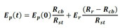
However, after corrosion begins, it can be seen in Figure 5 and Equation (12) that the particle size will represent both reinforcement and corrosion products. Thus, the particle Young’s modulus is corrected so the effects of reduction of steel are considered. It is then considered that the value of the particle Young’s modulus is given by Equation (13):
 |
(13) |
where Ep(0) is the initial particle Young’s modulus (uncorroded reinforcement), Ep(t) is the particle Young’s modulus at the instant t , Er is the rust Young’s modulus, Rst is the rebar initial radius, Rcb is the remaining rebar radius and Rr is the rust radius.
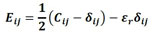
Finally, an additive decomposition of the Green strain is used to compose the concrete expansion due to formation of corrosion products, following Equation (14). This decomposition is possible since only small and moderate deformations are considered.
 |
(14) |
where Eij represents the elastic portion of the deformation and εr is the deformation of the particle (reinforcement) due to uniform corrosion for each of the main directions.
More details about the developed model, either of the formulation or of its applicability, can be obtained in Felix (2018).
3. Results
Initially, two numerical simulations are presented referring to laboratory tests of concrete elements submitted to accelerated corrosion. Then, uniform corrosion on a reinforced concrete structure are analyzed using the model developed. The analysis was performed considering two environments, laboratory (accelerated corrosion) and urban (natural corrosion).
3.1 Performance analysis and model validation - Example 1
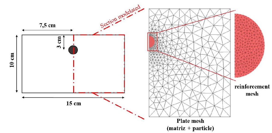
To demonstrate the efficiency of the model developed via MEFP to represent the expansion of concrete due to uniform corrosion, and especially, the formation of corrosion products, the modeling of a reinforced concrete plate under accelerated uniform corrosion is initially presented, which was experimentally analyzed by Nguyen et al. (2007).
 |
||||
| Figure 6. First example geometry and discretization | ||||
The plate contains a reinforcement with a diameter of 10 mm located in the central region, as shown in Figure 6, and was produced with concrete with compressive strength of 39 MPa and steel with a proportional limit of 500 MPa.
To achieve the accelerated corrosion test, Nguyen et al. (2007) subjected the reinforced concrete plate, after a 28-day wet cure, to a current with a constant density of 100 µA / cm² for 92 hours.
For numerical modeling, only half of the concrete plate was simulated (see Figure 6), due to symmetry of the problem. The plate was discretized by means of a particulate composite element, being used 680 triangular finite elements for the representation of the concrete matrix and 826 triangular finite elements for the discretization of the reinforcement.
Table 1 shows the parameters applied to model the problem, which were extracted from Nguyen et al. (2007).
| Table 1. Input parameters for the corrosion simulation. | ||
| Parameter | Value | Unity |
|---|---|---|
| Steel density | 7860 | kg/m³ |
| Valence | 2 | - |
| Density ratio of steel and corrosion products | 3.7 | - |
| Corrosion products, Young’s modulus | 0.15 | GPa |
| Atomic mass of steel | 55.84 | - |
| Expansion volume ratio of corrosion products | 3.7 | - |
It was adopted Young’s modulus of 25 GPa and Poisson ratio of 0.2 for concrete, and Young’s modulus of 210 GPa and Poisson ratio of 0.3 for steel.
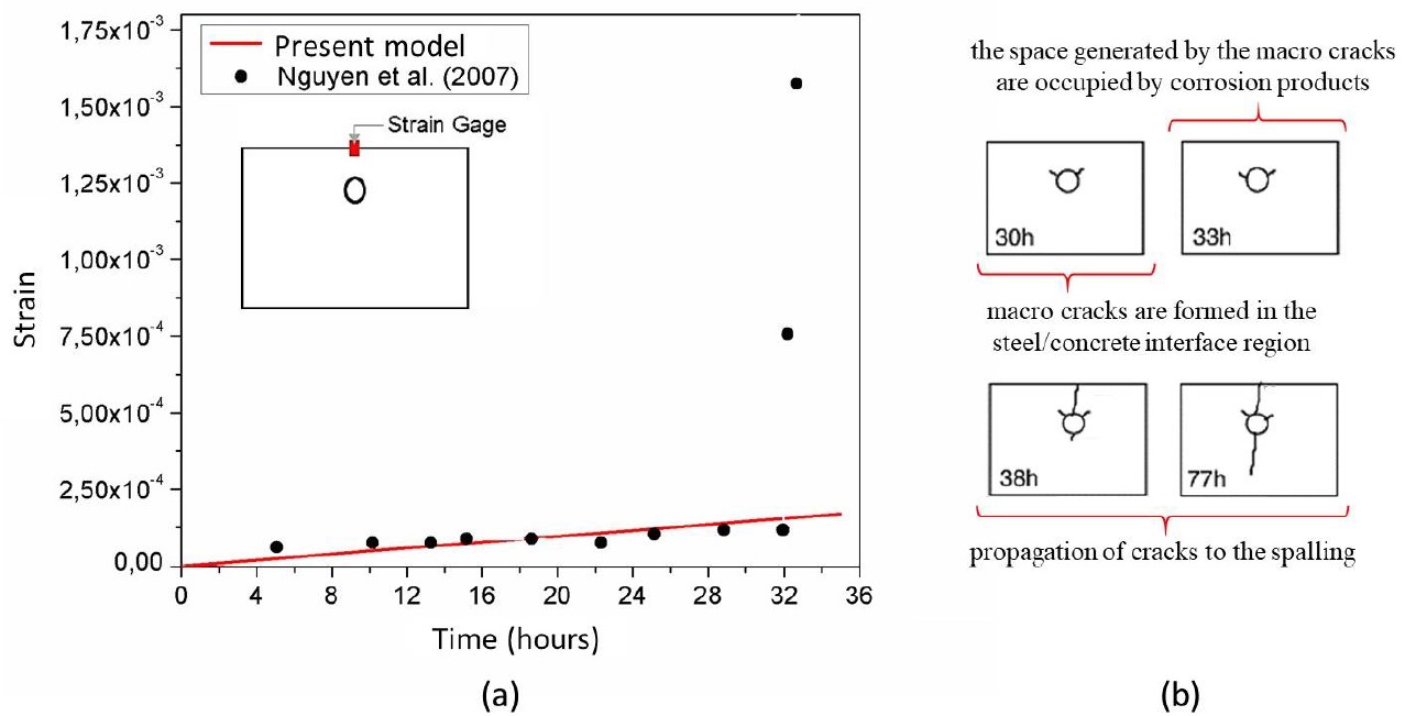
Figure 7a presents the strain measured in the plate upper region, comparing the results obtained by the numerical simulation and by the experimental program of Nguyen et al. (2007).
 |
||||
| Figure 7. (a) Strain development and (b) Cracking evolution by Nguyen et al. (2007). | ||||
Figure 7.a shows that the numerical results consistently represent the experimental evaluation of the concrete expansion due to uniform corrosion, presenting an average absolute deviation of 4.12%. Notice that, after 30 hours, Nguyen et al. (2007) found a sudden increase in strain, which the numerical model was unable to represent, due to macro cracks formed in the interface of steel and concrete - see Figure 7.b. This behavior cannot be simulated by the proposed model since only elastic strains are considered so far.
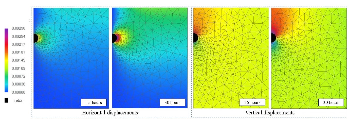
Figure 8 shows the horizontal and vertical displacements of the concrete slab after 15 and 30 hours of accelerated corrosion. One may notice that, only after 30 hours, significant deformations are observed on the surface.
 |
||||
| Figure 8. Displacement color maps (cm) | ||||
 |
||||
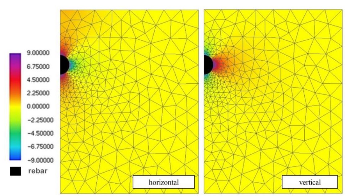
| Figure 9. Stress color maps (MPa). | ||||
Figure 9 shows the stress distribution in the horizontal and vertical directions after 30 hours of accelerated corrosion. As expected, it is possible to observe that the tensile stresses present values above 3 MPa, corresponding to the tensile strength of the concrete, which would imply the development of cracks and corroborating the conclusions of Nguyen et al. (2007).
Thus, the results demonstrate that the model consistently represents the uniform corrosion expansive effects.
3.2 Performance analysis and model validation - Example 2
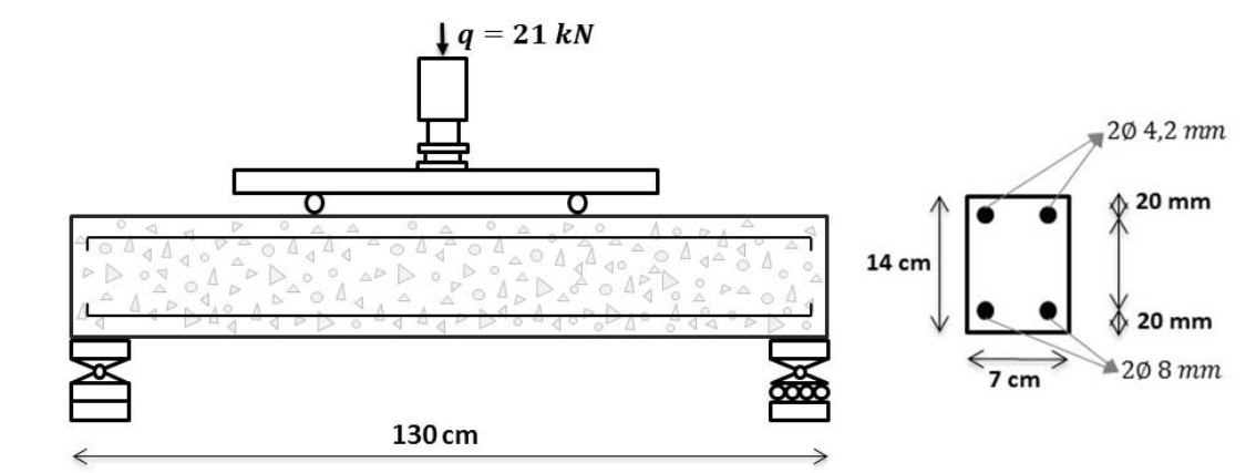
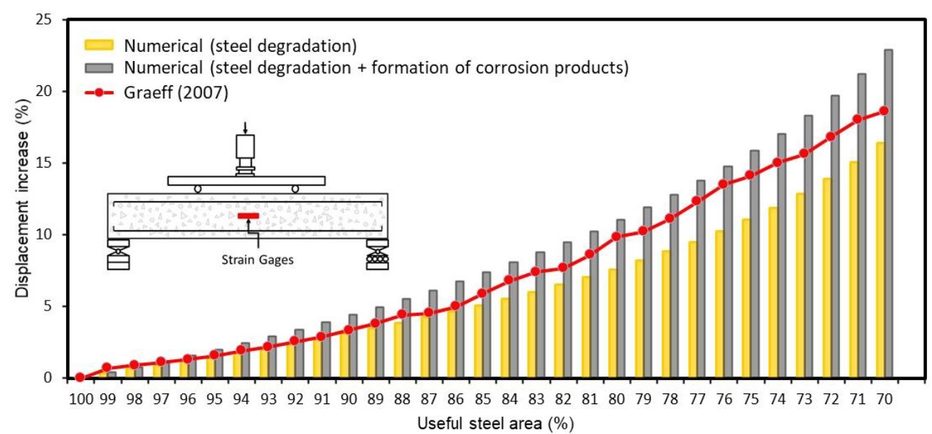
In the second example, a reinforced concrete beam is simulated, based in the experimental assessment of Graeff (2007), see Figure 10. The simply supported beam of length 130 cm has a rectangular cross section 7 cm wide and 14 cm high, with a span of 120 cm between supports, see Figure 10 for more details.
 |
||||
| Figure 10. Reinforced concrete beam details | ||||
The finite element mesh is composed of 134 nodes and 34 triangular elements of cubic approximation for the concrete matrix, and 340 triangular elements for the rebars. The following material properties are adopted for concrete: Young modulus of 2600.0 kN/cm², compressive strength of 2.5 kN/cm², tensile strength of 0.179 kN/cm² and Poisson’s ratio of 0.2. Young modulus of 210 MPa and tensile strength of 500 MPa are adopted for rebars. Graeff (2007) has also considered the nonlinear behavior of concrete, as well as the effects of corrosion, such loss of steel section and loss of steel-concrete bond.
 |
||||
| Figure 11. Comparison of beam displacement. | ||||
In this work, the simulation of corrosion was done considering two situations, one in which the effects of corrosion are related only to the loss of the steel section, and another in which the corrosion causes the loss of the steel section and the expansion of the concrete, due to the formation of corrosion products. By means of Figure 11, the results achieved with this work are compared with those determined in Graeff (2007). It can be seen from Figure 11 that the difference between the results obtained by the numerical model presented in this work (in the two simulations) and those obtained by Graeff (2007) is increasing, as the degradation of the reinforcements increases. An explanation for such a difference is because Graeff (2007) adopted in his model a nonlinear constitutive law for concrete and steel.
However, it is observed that all the curves have similar behavior in relation to displacements of the structure and that considering the initial period of corrosion (up to the moment when the reinforcement loses 15% of useful area), for cases in which the materials are still they work in a linear-elastic regime, the implemented model presents equivalent results to those of Graeff (2007).
By means of Figure 11 it is possible to see that the combined consideration of more than one corrosion degradation effect results in greater beam displacements and that, when considering the expansion of the concrete due to the formation of corrosion products, the Loss of concrete's mechanical capacity becomes greater with the advance of corrosion. This fact demonstrates the importance of considering this phenomenon in modeling the corrosion of concrete structures.
3.3 Analysis of mechanical behavior of corroded reinforced concrete beam
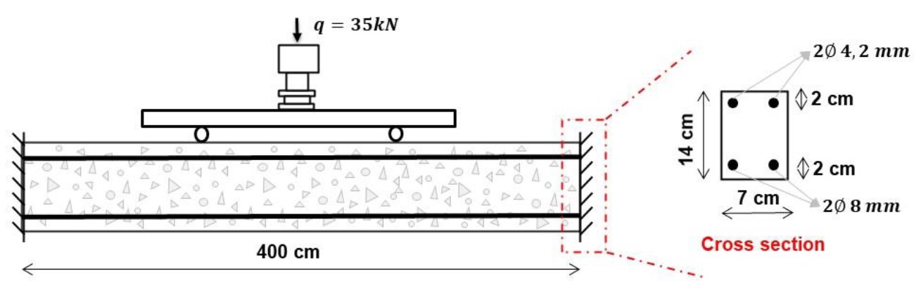
Third example consists of a clamped reinforced concrete beam under uniform corrosion. The objective of this analysis is to evaluate the effect of the corrosion on the displacement of the concrete structure, as well on the stress distribution. The beam geometry, dimensions, loading and boundary conditions are shown in Figure 12.
 |
||||
| Figure 12. Beam geometry, dimensions and boundary conditions. | ||||
Corrosion is initially imposed rapidly, using a constant current of 100 µA / cm². Next, the effects of simulated corrosion in a laboratory environment (accelerated corrosion) are evaluated, comparing it with the effects of natural corrosion, by means of a time-varying current, determined in accordance with equation (11). The parameters used in the formulation regarding the formation of the corrosion products, whose data were extracted from Nguyen et al. (2007) are described in Table 1.
The discretization of the finite element mesh of the reinforced concrete beam was made with 2230 knots and 468 triangular elements for the representation of the concrete matrix and with 952 triangular elements (particles) for the representation of the reinforcement. Regarding the properties of the materials, the concrete has a modulus of elasticity of 2600.0 kN / cm², compressive strength of 2.5 kN / cm², tensile strength of 0.179 kN / cm² and Poisson's ratio of 0.2. The reinforcements, in turn, have a modulus of elasticity of 21000 kN / cm² and tensile strength of 50 kN / cm².
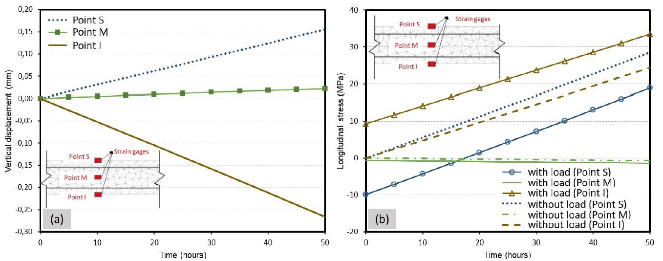
Figures 13.a and 13.b present the results referring to vertical displacement and longitudinal tension (for three different beam regions), considering the chemical-mechanical stresses (imposed by corrosion) and the stresses from the cargo.
It is noted in Figure 13.a that after 50 hours of accelerated corrosion, the structure experiences an increase in displacement of 0.26 mm (for low) for a point located in the lower part of the center of the beam (point "I"), as for a point located in the upper part of the center of the beam (point "S"), the increase was 0.14 mm, almost half of the value observed in the lower point.
 |
||||
| Figure 13. (a) Vertical displacement and (b) Longitudinal stresses | ||||
The results presented in Figure 13.b demonstrate the influence of corrosion on the beam stress field under corrosion when considering the application of an external load. It is observed for the case of only corrosion (without loading) that the stresses at points "S" and "I" are always tensile (regardless of the propagation time), as pointed out by Balafas and Burgoyne (2010). However, it is noted that in the presence of an external cargo, the voltage field begins to have behavior controlled by the level of corrosion of the armatures. For example, the “S” point, located at the top of the beam, has its state of compression stress altered for traction after 15 hours of accelerated corrosion.
In other words, it has been verified that there is a significant influence of corrosion on the stress fields of reinforced concrete beams in service (with cargo). This influence has secondary effects that corroborate with the reduction of the useful life of the structures, for example, cracking of the covering concrete. The cracking state of a reinforced concrete element is highly dependent on its stress state and, consequently, if corrosion alters the stress field of a structural element, it can modify and / or accelerate its rupture mechanisms.
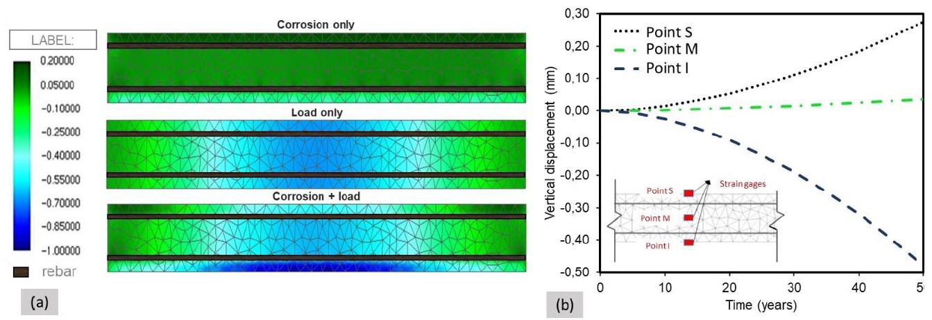
Figure 14.a shows the deformed configuration of the beam considering three different stress configurations: (i) only corrosion; (ii) only cargo; and (iii) joint action of cargo and corrosion. It is noted that in the case where the beam stresses are exclusively the result of corrosion, the entire structural element is stressed, due to the formation of corrosion products. It is still observed that the displacements of the beam in the case of corrosion and external loading can be described by overlapping mechanical (due to external loading) and chemical-mechanical stresses (resulting from corrosion).
Finally, Figure 14.b presents the results for the vertical displacement of the reinforced concrete beam, considering only natural corrosion.
Based on the results of the simulation of natural corrosion, which are presented in Figure 14.b, it was verified that the displacement of the “I” point after 50 years of natural corrosion is 0.47 mm, 79% greater than the displacement observed after 50 hours of accelerated corrosion.
 |
||||
| Figure 14. (a) Vertical beam displacement: (a) for 50 years e (b) at the time (mm). | ||||
4. Conclusions
The proposed model, based on the Positional Finite Element Method (Positional FEM), consistently represents the expansion of concrete due to the formation of corrosion products. The model has been validated, given the numerical simulations carried out, allowing to conclude that:
- Corrosion can significantly modify the stress distribution of a structural element, even imposing that a previous compressed region become tensioned;
- An external load does not change the fact that an element undergoes corrosion. The effects overlap, and the superposition tends to be meaningful;
- Displacements can be described by superposition of the mechanical loads and formation of corrosion products, before cracking;
- Significant differences are observed in the mechanical behavior of a structural element when exposed to natural or accelerated corrosion, and no correlation are directly found;
- As long as damage is not relevant, small strain may be assumed, and the superposition principle can be extended to evaluate the corrosion in reinforced concrete structures.
Finally, we conclude that the proposed model is a viable and efficient alternative for the simulation of reinforce concrete elements under uniform corrosion.
5. Acknowledgment
The research supported by the Brazilian National Council for Scientific and Technological Development (CNPq 141078/2018 e CNPq 310564/2018-2) is gratefully acknowledged. This study was also financed in part by the Coordenação de Aperfeiçoamento de Pessoal de Nível Superior - Brasil (CAPES) - Finance Code 001.
6. References
Almusallam, A. A. (2001), Effect of degree of corrosion on the properties of reinforcing steel bars. Construction and Building Materials. 15(8):361-368. https://doi.org/10.1016/S0950-0618(01)00009-5
Andrade, C., Alonso, C., Molina, F. J. (1993), Cover cracking as a function of bar corrosion: Part 1 Experimental test. Materials and Structures. 26:453-464. https://doi.org/10.1007/BF02472805
Balafas, I., Burgoyne, C. J. (2011), Modeling the structural effects of rust in concrete cover. Journal of Engineering Mechanics. Journal of Engineering Mechanics. 137(3):175-185. https://doi.org/10.1061/(ASCE)EM.1943-7889.0000215
Bhargava, K., Ghosh, A. K., Mori, Y., Ramanujam, S. (2005), Modeling of time to corrosion-induced cover cracking in reinforced concrete structures. Cement and Concrete Research. 35(11):2203-2218. https://doi.org/10.1016/j.cemconres.2005.06.007
Coda, H. B. (2018), “O método dos elementos finitos posicional: sólidos e estruturas - Não linearidade geométrica e dinâmica”. Publisher: EESC-USP, Place of publication: São Carlos, SP, p. 284. ISBN: 9788580230680
Du, X., Jin, L. (2014), Meso-scale numerical investigation on cracking of cover concrete induced by corrosion of reinforcing steel. Engineering Failure Analysis. 39:21-33. https://doi.org/10.1016/j.engfailanal.2014.01.011
Felix, E. F. (2018), “Modelagem da deformação do concreto armado devido à formação dos produtos de corrosão”. Master Thesis, Escola de Engenharia de São Carlos/USP, São Carlos.
Gentil, V. (2011), “Corrosão”. Editora LCT, 6º edição, Rio de Janeiro, Brasil, p. 376.
Graeff, A. G. (2007), “Avaliação experimental e modelagem dos efeitos estruturais da propagação da corrosão em elementos de concreto armado”. Master Thesis, Universidade Federal do Rio Grande do Sul, Porto Alegre.
Hansen, E. J., Saouma, V. E. (1999), Numerical simulation of reinforced concrete deterioration: Part 2-steel corrosion and concrete cracking. ACI Materials Journal. 96:331-338. ISSN: 0889-325X.
Helene, P. (1986), “Corrosão em armaduras para concreto armado”. PINI, São Paulo, Brasil. p. 46.
Isgor, O. B., Razaqpur, A. G. (2006), Modelling steel corrosion in concrete structures. Materials and Structures. 39(3):291-302. https://doi.org/10.1007/s11527-005-9022-7
Jiang, L., Lin, B., Cai, Y. (2000), A model for predicting carbonation of high-volume fly ash concrete. Cement and Concrete Research. 30(5):699-702. https://doi.org/10.1016/S0008-8846(00)00227-1
Kiani, K., Shodja, H. M. (2011), Prediction of the penetrated rust into the microcracks of concrete caused by reinforcement corrosion. Applied Mathematical Modelling. 35(5):2529-2543. https://doi.org/10.1016/j.apm.2010.11.039
Liu, Y., Weyers, R. E. (1998), Modeling the time-to-corrosion cracking in chloride contaminated reinforced concrete structures. Materials Journal. 95(6):675-680.
Maruya, T., Hsu, K., Takeda, H., Tangtermsirikul, S. (2003), Numerical modeling of steel corrosion in concrete structures due to chloride ion, oxygen and water movement. Journal of Advanced Concrete Technology. 1(2):147-160. https://doi.org/10.3151/jact.1.147
Mehta, P. K., Monteiro, P. J. M. (2014), “Concreto: microestrutura, propriedades e materiais”. Ibracon, São Paulo, Brasil, p. 751.
Molina, F. J., Alonso, C., Andrade, C. (1993), Cover cracking as a function of bar corrosion: Part 2-Numerical model. Materials and Structures. 26 :532-548. https://doi.org/10.1007/BF02472864
Nguyen, Q. T., Caré, S., Millard, A., Berthaud, Y. (2007), Analyse de la fissuration du béton armé en corrosion accélerée. Comptes Rendus Mecanique. 335(2): 99-104. https://doi.org/10.1016/j.crme.2007.01.005
Ožbolt, J., Oršanić, F., Balabanić, G. (2014), Modeling pullout resistance of corroded reinforcement in concrete: Coupled three-dimensional finite element model. Cement and Concrete Composites. 46:41-55. https://doi.org/10.1016/j.cemconcomp.2013.10.014
Paccola, R. R., Coda, H. B. (2016), A direct FEM approach for particulate reinforced elastic solids. Composite Structures. 45:235-251. https://doi.org/10.1016/j.compstruct.2016.01.062
Paul, S. C., Zijl, G. P. A. G. V. (2016), Chloride-induced corrosion modelling of cracked reinforced SHCC. Archives of Civil and Mechanical Engineering. 16(4):734-742. https://doi.org/10.1016/j.acme.2016.04.016
Ribeiro, D., Cunha, M., Helene, P. (2015), “Corrosão em Estruturas de Concreto Armado: Teoria, Controle e Métodos de Análise”. Elsevier Brasil, Campus, São Paulo, Brasil, p. 272.
Vanalli, L., Paccola, R. R., Coda, H. B. (2008), A simply way to introduce fibers into FEM models. Communications in Numerical Methods in Engineering. 24:585-603. https://doi.org/10.1002/cnm.983
Yuan, Y., Ji, Y. (2009), Modeling corroded section configuration of steel bar in concrete structure. Construction and Building Materials. 23(6):2461-2466. https://doi.org/10.1016/j.conbuildmat.2008.09.026
Zhu, W. (2014), “Effect of corrosion on the mechanical properties of the corroded reinforcement and the residual structural performance of the corroded beams”, Doctoral Dissertation, Institut National des Sciences Appliquées de Toulouse (INSA de Toulouse).