
| Basic Research | https://doi.org/10.21041/ra.v10i3.257 |
The importance of underpaint corrosion caused by damage to paint on steel structures
Importância da corrosão subpelicular por descontinuidade da película de pintura em estruturas de aço
Importancia de la corrosión subpelicular por discontinuidad de la película de pintura en estructuras de acero
G. L.
Ribeiro1
*
![]() , R. A. J. Ribas2
, R. A. J. Ribas2
![]() , G. D. Paula2
, G. D. Paula2
![]()
1 Federal Institute of Education, Science and Technology of Minas Gerais (IFMG), Belo Horizonte, Brazil.
2 Mining School, Federal University of Ouro Preto (UFOP), Ouro Preto, Brazil.
*Contact author: guidolessa@yahoo.com.br
Reception: October 03, 2018.
Acceptance: January 16, 2020.
Publication: September 01, 2020.
| Cite as: Ribeiro Filho, G. L., Ribas, R. A. J., Paula, G. D. (2020), "The importance of underpaint corrosion caused by damage to paint on steel structures", Revista ALCONPAT, 10 (3), pp. 286 – 299, DOI: https://doi.org/10.21041/ra.v10i3.357 |
Abstract
The impact of varying the dry paint film thickness (DFT) on the underpaint corrosion of steel plates obtained from the floor of an offshore oil platform is evaluated. The specimens were all prepared using the same material and paint scheme, and the DFT and exposure conditions in a salt spray chamber were varied and compared with the results obtained in a real situation. The results indicated that corrosion initiated at sites where the paint was damaged, may be more important than corrosion through the undamaged paint due to permeation, even in cases where the DFT is thin. In specimens whose substrates were previously damaged, there were pathological manifestations of osmotic blistering. The underpaint corrosion that occurred after the paint was damaged in the field occurred at an intensity like that observed for the tested specimens.
Keywords:
structures,
steel,
film,
painting,
corrosion.
Resumo
O trabalho avaliou impacto da variação da espessura da película seca de pintura (EPS) na corrosão subpelicular em chapas de aço do piso de uma plataforma de petróleo. Foram preparados corpos de prova (CPs) com material e esquema de pintura do projeto, com variação das EPS, exposição em câmara de névoa salina (salt spray) e comparados com situação real. Os resultados indicaram que corrosões iniciadas em danos à película podem ganhar maior importância que corrosões por permeabilidade através da película, mesmo as com baixa EPS, porém contínua. Em CPs com prévia contaminação do substrato, observaram-se manifestações patológicas de empolamento por osmose. A corrosão subpelicular a partir do rompimento da película em campo ocorreu numa intensidade semelhante aos CPs ensaiados.
Palavras-chave:
estruturas,
aço,
película,
pintura,
corrosão.
Resumen
El trabajo evaluó el impacto de la variación del grosor de la película de pintura seca (GPS) sobre la corrosión subpelicular en láminas de acero del piso de una plataforma petrolera. Se prepararon cupones de prueba (CP) con el esquema de pintura y material del proyecto, con variación de GPS, exposición en una cámara de niebla salina y comparación con la situación real de campo. Los resultados indicaron que la corrosión iniciada en el daño de la película puede ganar mayor importancia que la corrosión por permeación a través de aquella, inclusive en los lugares de GPS bajo, aunque sea continuo. En los CPs con contaminación previa del sustrato, hubo manifestaciones patológicas de ampollas osmóticas. La corrosión subpelicular de la ruptura de la película de campo se produjo a una intensidad similar a la de los CPs probados.
Palabras clave:
estructuras,
acero,
película,
pintura,
corrosión.
1. Introduction
Corrosion is a spontaneous process in which metals deteriorate, resulting in chemical and/or electrochemical changes that tend to bring the metals back to their original state, which releases the energy applied in the metallurgy process. The corroded metal in a lower energy state returns to the most primitive state of the metal and loses the properties it acquired during the metallurgy process, such as its mechanical strength, elasticity, ductility, aesthetics and other characteristics, which vary according to the type of alloy. The product resulting from the corrosion process is the ore itself, i.e., oxides, hydroxides, carbonates, sulfides, sulfates, silicates, etc. (Silva, 1981; Ramanathan, 1988; Gentil, 2007; Nunes and Lobo, 2007).
A relevant engineering factor of the corrosion process is the speed with which corrosion occurs. By assuming that every metal can be used in any medium as long as the corrosion rate is compatible with the application, the economic viability of less noble metals can be ensured for certain uses. Thus, steel can be widely used in structures if proper anticorrosion protection is applied through painting, coating, galvanization, and metallization, among other processes (Silva, 1981).
Atmospheric corrosion occurs basically by the electrochemical mechanism. This mechanism is most frequently observed in nature and is characterized by the presence of liquid water and temperatures below the dew point (usually room temperature) and occurs due to the formation of electrochemical corrosion cells or batteries. Thus, it is understood that electrons move from one area of the metallic material to another by means of an aqueous solution capable of conducting electricity, i.e., salts or ions must exist in the liquid water (electrolytes), causing oxidation reactions at one site and reduction reactions at another site (Nunes and Lobo, 2007). The water molecules are polar and aggregates to the metal ions of the metal that contact the electrolyte, forming ions (aggregates of this metal without its valence electrons), and this reaction results in the dissolution of the metal; that is, corrosion is a destructive chemical reaction that occurs between the metal or metal alloy and the environment (Wolynec, 2003; Jones, 1996).For corrosion to occur, the substrate must contact the electrolyte; hence, metal corrosion protection is important.
In general, industrial, naval and civil structures use paint as a form of protection, which, when properly applied, offers good protection at a reasonable cost. The contact between the electrolyte and the substrate, which is capable of initiating the corrosion process, may occur due to the paint permeability (caused by failures in the paint due to the painting process, such as thin coatings or a high porosity), corrosive agents in the medium attacking the paint (caused by an incorrect choice of paint type) or paint damaged mechanically, which causes most of the corrosion observed in the studied offshore platform. The damaged paint eliminates the barrier protection and allows the corrosive agent to contact the substrate; in addition, paint damage causes the loss of protection by the corrosion inhibitors that may be present in the paint formulation (Chawla and Gupta, 1995).
According to Chawla and Gupta (1995), paint resists the passage of corrosive agents and reduces the ionic movement that permeates the corrosive agents; however, the resistance offered is not good enough to inhibit corrosion.
The paint type and dry film thickness (DFT) must be compatible with the corrosive agents present in the medium, and a thickness of 250 μm is recommended for highly aggressive atmospheres, as is the case for petroleum platforms installed in marine environments (Nunes and Lobo, 2007).
In this context, the objective of this study was to evaluate the impact of varying the DFT on underpaint corrosion in steel plates obtained from the floor of an offshore oil platform.
2. Methodology
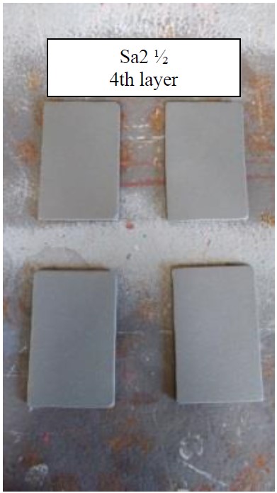
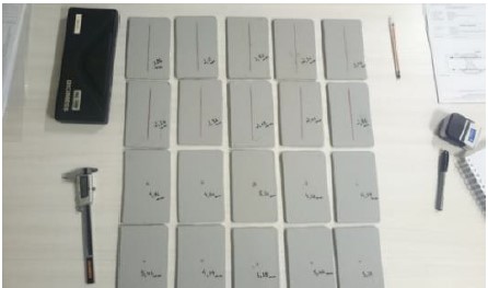
In this methodology, the underpaint corrosion of the specimens was compared with that observed for the case study of an oil platform. The specimens, with dimensions of 150 mm x 100 mm x 6.3 mm, were prepared from floor plates used to construct the platform (steel NV-A36), and the paint scheme provided in the painting procedure with some thickness variations was used (Figure 1). These specimens had damaged paint (carvings) and were subjected to a salt spray test for 1550 h to evaluate the effects of the DFT on underpaint corrosion.
2.1 Preparation of the specimens
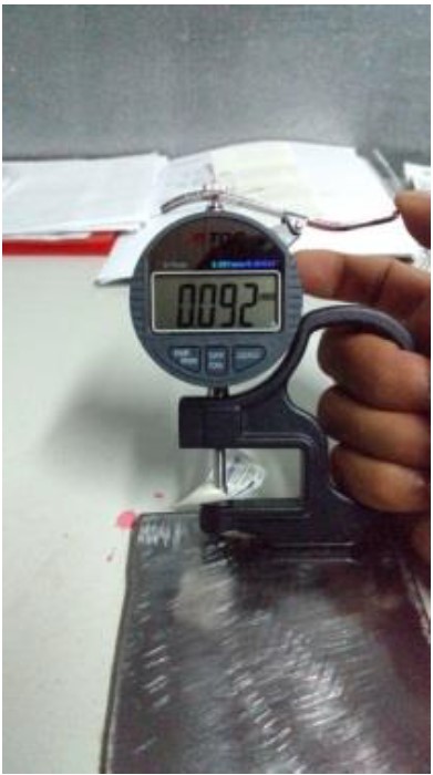
Six groups of specimens were prepared, where groups 1 to 5 were composed of four specimens each (named A, B, C and D), and group 6 was composed of only two specimens (named A and B). All specimens were previously washed with clean water. The specimens from groups 1 and 2 were previously subjected to St3 and Sa2½ surface preparation methods, respectively, according to standard ISO 8501-1 (ISO, 2007) and standard NBR 10443 (ABNT, 2008), respectively, and were then subjected to a small thickness coating system. Groups 3 and 4 were subjected to St3 and Sa2½ surface preparation methods, respectively, and a complete paint system was used to apply the paint to the atmospheric zone2 (Table 1); according to the painting procedure used for the project, which expects a DFT between 445 μm and 600 μm, the DFT was measured for each layer. Prior to painting, the roughness of all specimens was measured after the Sa2½ preparation method was performed to verify if the DFT requirement of 50 μm to 100 μm, as predicted in the painting procedure of the project, was met (Figure 2).
 |
||||
| Figure 1. Plates prepared with a Sa2½ abrasive jet (Ribeiro Filho, 2018) | ||||
 |
||||
| Figure. 2. Roughness meter used to measure the roughness of a St3 standard plate (Ribeiro Filho, 2018) | ||||
| Table 1. Painting scheme used for the atmospheric zone | ||||||||||||||
| SURFACE TREATMENT | ||||||||||||||
|---|---|---|---|---|---|---|---|---|---|---|---|---|---|---|
| Operation temperature | Preparation treatment | Soluble salts in water | Roughness profile | |||||||||||
| Up to 80oC | Sa2½ | < 5µg/cm2 | 50µm to 100µm | |||||||||||
| PAINT APPLICATION | ||||||||||||||
| Number of coatings | Paint | DFT 2 (µm) | Color | Methad of application | Paint interval | |||||||||
| Minimum | Maximum | Minimum | Maximum | |||||||||||
| 1 | N-2680 Expoxy without solvents 3 | 135 | 180 | Red | Roll/brush without air gun | 12 h | 120 h | |||||||
| 2 | N-2680 Expoxy without solvents | 135 | 180 | Ligth gray | Roll/brush without air gun | 12 h | 120 h | |||||||
| 3 | N-2680 Expoxy without solvents | 135 | 180 | Ligth gray | Roll/brush without air gun | 12 h | 120 h | |||||||
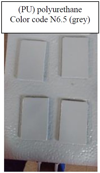
| 4 | N-2677 Polyurethane 4 | 40 | 60 | According to local | Roll/brush spray gun | - | - | |||||||
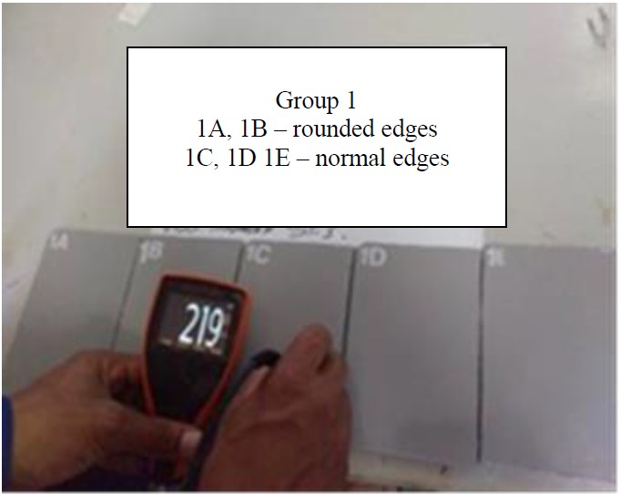
The surfaces of the specimens that received the St3 treatment were treated according to the standard ISO 8501-1 (ISO, 2007); the surfaces of the specimens that received the Sa2½ treatment were treated according to the standard NBR 15239 (ABNT, 2005). After each paint coating, the DFT was measured according to the standard NBR 10443 (ABNT, 2008), and the results of the preparation method are presented in Table 2. Figures 3 and 4 show images of the paint and the DFT measurement.
| Table 2. Preparation of the test specimens | |||||||||||||||
| NaCl | Salt test | N-2680 | N-2680 | N-2680 | N-2677 | Mean DFT | |||||||||
|---|---|---|---|---|---|---|---|---|---|---|---|---|---|---|---|
| Group | 1 | 2 | 3 | 4 | 5 | 6 | 7 | 8 | 9 | 10 | 11 | 12 | 13 | 14 | |
| 1 | B | St3 | 42 µm* | no | < 5µg/cm2 | x | 136 µm | - | - | - | - | x | 31 µm | 167 µm | |
| 2 | B | Sa2½ | 72 µm | no | < 5µg/cm2 | x | 119 µm | - | - | - | - | x | 55 µm | 174 µm | |
| 3 | B | St3 | N/A | no | < 5µg/cm2 | x | 138 µm | x | 115 µm | x | 229 µm | x | 69 µm | 551 µm | |
| 4 | B | Sa2½ | 68 µm | no | < 5µg/cm2 | x | 154 µm | x | 149 µm | x | 203 µm | x | 72 µm | 578 µm | |
| 5 | A | Sa2½ | 65 µm | yes | 19µg/cm2 | x | 110 µm | - | - | - | - | x | 60 µm | 170 µm | |
| 6 | D | St3 | N/A | no | < 5µg/cm2 | x | 210 µm | - | - | - | - | x | 73 µm | 283 µm | |
Index of the columns in Table 2
Column 1 - Degree in which the plate was corroded before preparation, according to the photographic standard of ISO 8501-1 (ISO, 2007).
Column 2 - Surface preparation treatment according to the standard ISO 8501-1 (ISO, 2007), which was applied by a rotating mechanical tool with 24 grit sanding discs, according to standard BR 15239 (ABNT, 2005) for the St3 treatment and standard N-9 (PETROBRAS, 2006) for the Sa2½ treatment.
Column 3 - Result of the roughness test according to standard SP-0287 (NACE, 2016).
Column 4 - Was NaCl contamination performed prior to painting?
Column 5 - Result of the salt test of the contaminated surfaces, according to ISO 8502-6 (ISO, 2006).
Column 6 - The first coat of the N-2680 paint was applied.
Column 7 - The DFT of the first coat of the N-2680 paint.
Column 8 - The second coat of the N-2680 paint was applied.
Column 9 - The DFT of the second coat of the N-2680 paint.
Column 10 - The third coat of the N-2680 paint was applied.
Column 11 - The DFT of the third coat of the N-2680 paint.
Column 12 - The final coat of the N-2677 paint was applied.
Column 13 - The DFT of the final paint coating.
Column 14 - The total DFT.
*For surface treatment St3, a roughness test is not applicable; however, a roughness measurement was performed for group 1 to verify the effectiveness of the treatment.
Notes:
 |
||||
| Figure 3. Finishing the paint (Ribeiro Filho, 2018). | ||||
 |
||||
| Figure 4. Measuring the total DFT (Ribeiro Filho, 2018). | ||||
Unlike groups 1, 2, 3 and 4, in which a corrosion grade B plate was used, a corrosion grade A plate was used in group 5, which was contaminated with sodium chloride after the preparation treatment was applied with the Sa2½ standard abrasive jet, and subsequently, thin paint layers were applied. After contamination, the salinity on the surface of the specimens was measured to be 19 µg/cm2, which was verified according to the standards ISO 8502-6 (ISO, 2006) (salt test) and ISO 8502-9 (ISO, 1998) and was higher than the maximum limit for structures located in the atmospheric zone, which, in this case, cannot exceed 5 µg/cm2.
The presence of sodium chloride at the beginning of and during the corrosion process is decisive regarding the exposure to weathering. (Sosa et al., 2018).
For group 6, only two specimens were prepared using corrosion grade D plates to verify the corrosion behavior in a specific situation of thin thickness on the convex surface, i.e., the paint on the weld points on the surface of the plate.
After painting, the paint layers were carved to simulate experimental damage/defects in the paint applied to the specimens from all groups; some of the carvings were longitudinal, and some were puncture carvings with 5 mm diameters, as shown in Figure 5.
2.2 Salt spray chamber
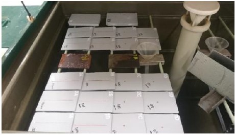
All specimens were subjected to a salt spray chamber (Figure 6) with a 5% sodium chloride (NaCl) saline mist, in which the mist was uniformly sprayed at a controlled temperature, according to ISO 9227 (ISO, 2012), NBR-8094 (ABNT, 1983) and B117-16 (ASTM, 2001). The temperature was maintained within the interval of 35 ± 2(C, and the specimens remained in the salt spray chamber for 1550 h.
 |
||||
| Figure 5. Specimens with experimentally damaged paint (Ribeiro Filho, 2018). | ||||
 |
||||
| Figure 6. Specimens in the salt chamber before exposure to the mist (Ribeiro Filho, 2018). | ||||
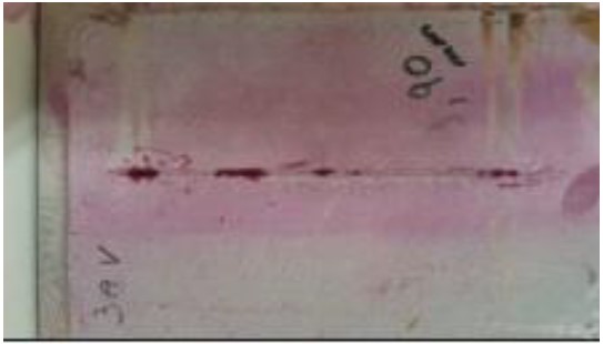
2.3 Penetrant liquid test
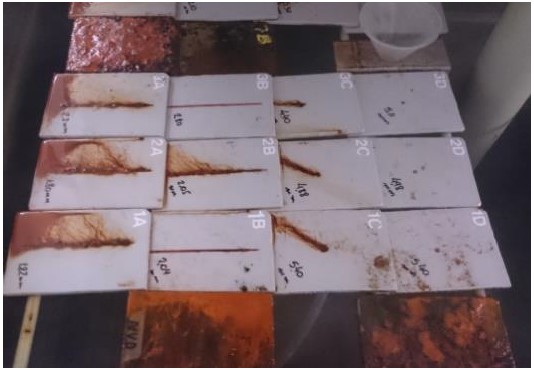
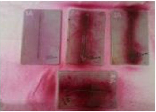
After removing the specimens from the saline chamber (Figure 7), the specimens were washed with clean running water at room temperature (<40°C) to remove the salt deposits and immediately dried. Subsequently, the specimens were subjected to a penetrant liquid (PL) test, according to the standard NBR 9583 (ABNT, 1997), and the points of higher corrosion incidence were determined (Figures 8 and 9).
These points were selected, and the specimens were cross-sectioned at those points (Figure 10). The cross-sections were observed under an LBM-044 microscope/stereoscope to measure the extent of the underpaint corrosion.
 |
||||
| Figure 7. Specimens after the 1550 h exposure (Ribeiro Filho, 2018). | ||||
 |
||||
| Figure 8. PL test awaiting development (Ribeiro Filho, 2018). | ||||
 |
||||
| Figure 9. Specimen awaiting development (Ribeiro Filho, 2018). | ||||
 |
||||
| Figure 10. Specimen sectioned for microscopy observation (Ribeiro Filho, 2018). | ||||
3. Results
Three underpaint corrosion measurements were performed for each section, and the results are shown in Table 3.
| Table 3. Underpaint corrosion measurements of the specimens | ||||||||||||
| Damage to the paint before the salt spray test | Corrosion extent (mm) | |||||||||||
|---|---|---|---|---|---|---|---|---|---|---|---|---|
| Group | Specimen | Degree of corrosion | Surface treatment | DFT (µm) | Damage created | Width of the damage (mm) | Ø of the damage (mm) | Depth of the damage | Measurement 1 | Measurement 2 | Measurement 3 | Mean |
| 1 | 1A | B | St3 | 167 | longitudinal | 2 | - | reached the substrate | 1,120 | 0,705 | 0,890 | 0,91 |
| 1B | B | longitudinal | 2 | - | preserved bottom paint layer | 0,000 | 0,000 | 0,000 | 0,00 | |||
| 1C | B | puncture | - | 5 | reached the substrate | 0,963 | 1,582 | 2,120 | 1,56 | |||
| 1D | B | puncture | - | 5 | preserved bottom paint layer | 0,000 | 0,000 | 0,000 | 0,00 | |||
| 2 | 2A | B | Sa2½ | 174 | longitudinal | 2 | - | reached the substrate | 0,888 | 1,060 | 0,390 | 0,78 |
| 2B | B | longitudinal | 2 | - | preserved bottom paint layer | 0,000 | 0,000 | 1,010 | 0,34 | |||
| 2C | B | puncture | - | 5 | reached the substrate | 0,550 | 1,711 | 1,084 | 1,12 | |||
| 2D | B | puncture | - | 5 | preserved bottom paint layer | 0,000 | 0,000 | 0,000 | 0,00 | |||
| 3 | 3A | B | St3 | 551 | longitudinal | 2 | - | reached the substrate | 1,034 | 1,19 | 1,175 | 1,13 |
| 3B | B | longitudinal | 2 | - | preserved bottom paint layer | 0,000 | 0,000 | 0,000 | 0,00 | |||
| 3C | B | puncture | - | 5 | reached the plate (substrate) | 1,273 | 1,041 | 0,880 | 1,06 | |||
| 3D | B | puncture | - | 5 | preserved bottom paint layer | 0,000 | 0,000 | 0,000 | 0,00 | |||
| 4 | 4A | B | Sa2½ | 578 | longitudinal | 2 | - | reached the substrate | 1,038 | 1,170 | 0,585 | 0,93 |
| 4B | B | longitudinal | 2 | - | preserved bottom paint layer | 0,000 | 0,000 | 0,000 | 0,00 | |||
| 4C | B | puncture | - | 5 | reached the substrate | 0,000 | 0,930 | 1,160 | 0,70 | |||
| 4D | B | puncture | - | 5 | preserved bottom paint layer | 0,000 | 0,223 | 0,000 | 0,07 | |||
| 5 | 5A | A | Sa2½ | 170 | longitudinal | 2 | - | reached the substrate | 1,195 | 0,950 | 0,490 | 0,88 |
| 5B | A | longitudinal | 2 | - | preserved bottom paint layer | 0,000 | 0,000 | 0,780 | 0,26 | |||
| 5C | A | puncture | - | 5 | reached the substrate | 1,049 | 1,238 | 1,120 | 1,14 | |||
| 5D | A | puncture | - | 5 | preserved bottom paint layer | 0,000 | 0,000 | 0,000 | 0,00 | |||
| 6 | 6A | D | St3 | 283 | puncture | - | 5 | reached the substrate | - | - | - | 0,81 |
| 6B | D | puncture | - | - | preserved bottom paint layer | - | - | - | 0,00 | |||
3.1 Analysis of the results
The results showed that no corrosion occurred, or it reached very low levels in cases where there was at least a continuous bottom paint layer; this happened even when the surface was prepared with the St3 preparation treatment and the paint was thin (Table 3). In turn, in all cases where the paint layer was discontinuous and the substrate was exposed to the medium, the corrosion advanced under the paint, almost identically, by approximately 1 mm for the 1550 h exposure, i.e., a rate on the order of 6.5 x 10⁻⁴ mm/h.
Tables 4, 5 and 6, which were obtained from Table 3, show that a mean corrosion extent of 0.96 mm was obtained for groups 3 and 4 (complete paint system), and a mean corrosion extent of 1.03 mm was obtained for groups 1, 2 and 63 (thin thickness) (Tables 4 and 5). Even in the case of group 5, in which the paint was thin and the surface was contaminated with NaCl, the mean corrosion extent (1.01 mm) was close to that obtained for the other groups (Table 6), which can be attributed to the low degree of corrosion penetration under the paint (despite contamination) and the use of a corrosion grade A plate. This was the only group that exhibited blistering4, with sparse bubbles on the surface of the plate, which is probably due to the osmosis caused by the paint under saline contamination conditions.
| Table 4. Corrosion of the specimen - Thin paint coatings | ||||||||||||||
| Damage to the paint coating before the salt spray test | Corrosion extent (mm) | Mean corrosion extent (mm) for specimens with a thin DFT | ||||||||||||
|---|---|---|---|---|---|---|---|---|---|---|---|---|---|---|
| Group | Specimen | Degree of corrosion | Surface treatment | DFT (µm) | Damage created | Width of the damage (mm) | Ø of the damage (mm) | Depth of the damage | Measurement 1 | Measurement 2 | Measurement 3 | Mean | ||
| 1 | 1A | B | St3 | 167 | longitudinal | 2 | - | reached the substrate | 1,120 | 0,705 | 0,890 | 0,91 | 1,03 | |
| 1B | B | longitudinal | 2 | - | preserved the bottom paint layer - paint intact | 0,000 | 0,000 | 0,000 | 0,00 | |||||
| 1C | B | puncture | - | 5 | reached the substrate | 0,963 | 1,582 | 2,120 | 1,56 | |||||
| 1D | B | puncture | - | 5 | preserved the bottom paint layer - paint intact | 0,000 | 0,000 | 0,000 | 0,00 | |||||
| 2 | 2A | B | Sa2½ | 174 | longitudinal | 2 | - | reached the substrate | 0,888 | 1,060 | 0,390 | 0,78 | ||
| 2B | B | longitudinal | 2 | - | preserved the bottom paint layer - paint intact | 0,000 | 0,000 | 1,010 | 0,34 | |||||
| 2C | B | puncture | - | 5 | reached the substrate | 0,550 | 1,711 | 1,084 | 1,12 | |||||
| 2D | B | puncture | - | 5 | preserved the bottom paint layer - paint intact | 0,000 | 0,000 | 0,000 | 0,00 | |||||
| 6 | 6A | D | St3 | 283 | puncture | - | 5 | reached the substrate | - | - | - | 0,81 | ||
| Table 5. Corrosion in specimen with complete system - Thick paint coating | ||||||||||||||
| Damage to the paint film before the salt spray test | Corrosion extent (mm) | Mean corrosion extent (mm) for specimens with a thick DFT | ||||||||||||
|---|---|---|---|---|---|---|---|---|---|---|---|---|---|---|
| Group | Specimen | Degree of corrosion | Surface treatment | DFT (µm) | Damage created | Width of the damage (mm) | Ø of the damage (mm) | Depth of the damage | Measurement 1 | Measurement 2 | Measurement 3 | Mean | ||
| 3 | 3A | B | St3 | 551 | longitudinal | 2 | - | reached the substrate | 1,034 | 1,19 | 1,175 | 1,13 | 0,96 | |
| 3C | B | puncture | - | 5 | reached the substrate | 1,273 | 1,041 | 0,880 | 1,06 | |||||
| 4 | 4A | B | Sa2½ | 578 | longitudinal | 2 | - | reached the substrate | 1,038 | 1,170 | 0,585 | 0,93 | ||
| 4C | B | puncture | - | 5 | reached the substrate | 0,000 | 0,930 | 1,160 | 0,70 | |||||
| Table 6. Corrosion in specimen with incomplete system and NaCl contamination | ||||||||||||||
| Damage to the paint film before the salt spray test | Corrosion extent (mm) | Mean (mm) for specimens with a thin thickness and NaCl | ||||||||||||
|---|---|---|---|---|---|---|---|---|---|---|---|---|---|---|
| Group | Specimen | Degree of corrosion | Surface treatment | DFT (µm) | Damage created | Width of the damage (mm) | Ø of the damage (mm) | Depth of the damage | Measurement 1 | Measurement 2 | Measurement 3 | Mean | ||
| 5 | 5A | A | Sa2½ | 170 | longitudinal | 2 | - | reached the substrate | 1,195 | 0,950 | 0,490 | 0,88 | 1,01 | |
| 5B | A | longitudinal | 2 | - | preserved the bottom layer - paint intact | 0,000 | 0,000 | 0,780 | 0,26 | |||||
| 5C | A | puncture | - | 5 | reached the substrate | 1,049 | 1,238 | 1,120 | 1,14 | |||||
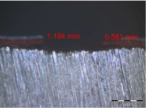
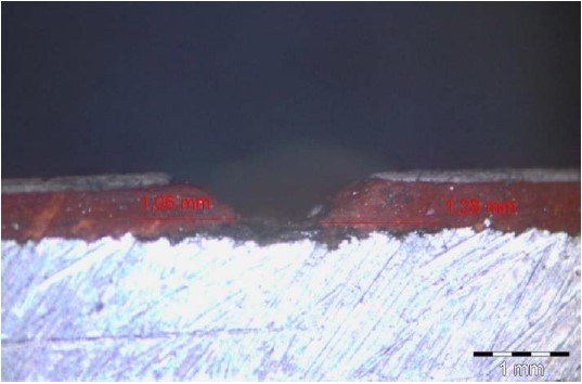
For example, the observations made using a microscope, as illustrated in Figures 11 and 12, showed that in cases where the paint damage reached the substrate, corrosion occurred in both of the complete paint schemes (specimen 4A) and the thin-thickness scheme (specimen 2A), both of which used surface preparation treatment Sa2½, which offers greater adherence.
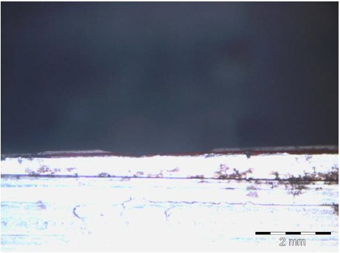
In contrast, specimen 1B (Figure 13), which was prepared with a thin DFT and received previous paint damage but had the bottom paint layer preserved, exhibited corrosion after 1550 h. For similar cases, there was an exception only for specimens 2B, 4D and 5B, where reduced corrosion was observed, and this occurred only in one of the three measurements shown in bold in Table 3. It was therefore concluded that when the surface preparation treatment (the standard St3 or Sa2½ treatment) is well performed, the electrolyte tends to access the substrate by the discontinuous paint if the paint exhibits a low permeability and porosity and receives a low peak exposure, as was the case for the specimens prepared for this study, and the resulting corrosion rate is similar for all the cases presented, even when the paint thicknesses are significantly different for the considered exposure time (1550 h).
Figure 14 shows the image of specimen 6A, in which the paint thickness on a welded point varied significantly. However, due to its integrity, the anticorrosion protection of the system was preserved, even with a film thickness of 283 μm.
 |
||||
| Figure 11. Underpaint corrosion measurement performed on specimen 2A (Ribeiro Filho, 2018). | ||||
 |
||||
| Figure 12. Underpaint corrosion measurement performed on specimen 4A (Ribeiro Filho 2018). | ||||
 |
||||
| Figure 13. Underpaint corrosion measurement performed on specimen 1B (Ribeiro Filho, 2018). | ||||
 |
||||
| Figure 14. Cross section of specimen 6A (Ribeiro Filho, 2018). | ||||
3.2 Analyzing an example obtained from the field survey
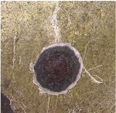
To compare the results obtained in the laboratory with those of a real platform situation, a surface with intact paint, except for a single isolated region of mechanical damage throughout the film, was identified during the field visit. By radially removing the paint from this central point, the limits of corrosion exhibited a circumferential configuration, denoting that equal corrosion occurred in all directions, which can be verified by the existence of sandblasting steel without corrosion, exhibiting a Sa2½ pattern from the limits of the corrosion edge, which reached a radius of 21 mm (Figures 15 and 16).
 |
||||
| Figure 15. Mechanical damage to the field paint (Ribeiro Filho, 2018). | ||||
 |
||||
| Figure 16. Edge of the corroded area and the area without corrosion (Ribeiro Filho, 2018). | ||||
Considering that the exact date of the damage or the beginning of the exposure is not known and that, in the worst scenario, the damage occurred on the day of the platform shutdown, which represents a period of approximately three years (3x8760 h), the mean corrosion rate was 8x10⁻⁴ mm/h, which is considered close to the value found in the laboratory (6.5x10⁻⁴ mm/h).
4. Conclusions
The results showed that once the substrate is exposed, the paint damage has a great impact on the underpaint corrosion.
The groups of specimens that were prepared with thin paint layers or whose paint was damaged without damaging the first coat maintained their ability to impart anticorrosion protection to the substrate, and the results were similar to those obtained for a specimen obtained in a field survey on the platform.
An exception was only observed for the group in which saline contamination was introduced into the substrate, which, in this case, showed that corrosion was favored by osmosis in the form of blistering.
Performing with the complete system without pathological manifestations, as well as preserving the quality and integrity of the paint, can ensure adequate anticorrosion protection. However, analyzing the results shows that the paint integrity had a decisive influence on the anticorrosion protection ability of the paint. In addition, considering the exposure time of 1550 h and the paint layers exhibiting no other pathological manifestations (porosity, corrosion attack, etc.), the paint integrity was also more important than the DFT. In situations where at least the first coat of paint was undamaged, the substrate was protected against corrosion when exposed to a salt chamber for 1550 h, even for the groups with thin paint thicknesses (< 250 μm). When the damage reached the substrate, the rate of underpaint corrosion was similar in all cases.
5. Acknowledgments
The authors thank the Brazilian Federal Agency for the Support and Evaluation of Graduate Education (CAPES), the Federal University of Ouro Preto, Techint Engenharia e Construção S/A and the Federal Institute of Education, Science and Technology (MG), Campus Congonhas.
References
Associação Brasileira de Normas Técnicas. (1983). NBR 8094: Material metálico revestido e não revestido - Corrosão por exposição à névoa salina. Rio de Janeiro.
Associação Brasileira de Normas Técnicas. (1997). NBR 9583. Implantes para cirurgia - Ensaio não-destrutivo - Inspeção por líquido penetrante de implantes cirúrgico metálicos. Rio de Janeiro.
Associação Brasileira de Normas Técnicas. (2005). NBR 15239: Tratamento de superfícies de aço com ferramentas manuais e mecânicas. Rio de Janeiro.
Associação Brasileira de Normas Técnicas. (2008). NBR 10443: Tintas e vernizes - Determinação da espessura da película seca sobre superfícies rugosas - Método de ensaio. Rio de Janeiro.
ASTM International. (2001). B117-16: Standard Practice for Operating Salt Spray (Fog) Apparatus. West Conshohocken, PA.
Chawla, S. L, Gupta, K. K. (1995), “Materials selection for corrosion control”, Materials Park, OH, ASM International.
Gentil, V. (2007), “Corrosão”, 5. ed., LTC Livros Técnicos e Científicos Editora S.A., Rio de Janeiro.
ISO (1998). ISO 8502-9: Preparation of steel substrates before application of paints and related products - Tests for the assessment of surface cleanliness - Part 9: Field method for the conductometric determination of water-soluble salts. Geneva, Switzerland.
ISO (2006). ISO 8502-6: Preparation of steel substrates before application of paints and related products - Tests for the assessment of surface cleanliness - Part 6: Extraction of soluble contaminants for analysis - The Bresle method. Geneva, Switzerland. DOI: https://dx.doi.org/10.31030/9727591
ISO (2007). ISO 8501-1: Preparation of steel substrates before application of paints and related products - Visual assessment of surface cleanliness - Part 1: Rust grades and preparation grades of uncoated steel substrates and of steel substrates after overall removal of previous coatings. Geneva, Switzerland. DOI: https://dx.doi.org/10.31030/9871577
ISO (2012). ISO 9227: Corrosion tests in artificial atmospheres - Salt spray tests. 3rd ed. Geneva, Switzerland.
Jones, D. A. (1996), “Principles and prevention of corrosion”, 2nd ed., Prentice-Hall Inc, New York, University of Nevada, Nevada.
Nunes, L. D. P., Lobo, A. C. O. (2007), “Pintura industrial na proteção anticorrosiva”, 3. ed., COPPE/UFRJ, Rio de Janeiro.
Ramanathan, L. V. (1988), “Corrosão e seu controle”, Editora Hemus, Rio de Janeiro.
Ribeiro Filho, G. L. (2018), “Estudo de patologias de pintura e corrosão atmosférica em plataforma de petróleo”, Dissertação de Mestrado, Universidade Federal de Ouro Preto.
Silva, P. F. D. (1981), “Introdução à corrosão e proteção de superfícies metálicas”, Imprensa Universitária da UFMG, Belo Horizonte.
Sosa, M. R., Pérez, T., Moo-Yam, V. M. J., Chávez, E. and Pérez-Quiroz, J. T. (2018), “Análise da interface concreto-aço em corpos de prova expostos à intempérie e imersos em água do mar natural”, Revista ALCONPAT, 8 (1), pp. 16-29, DOI: http://dx.doi.org/10.21041/ra.v8i1.203
Wolynec, S. (2003), “Técnicas Eletroquímicas em Corrosão”, Editora da Universidade de São Paulo, São Paulo.
Notes
2 Atmospheric zone – Elements of the platform that are located above sea level.
3 Group 6 was considered together with the systems receiving the thin thicknesses due to its proximity to the minimum DFT desired for highly aggressive environments (250 µm).
4 Blistering – Pathology of the paint known as blistering, or bubbles, which appear as semi-spherical protrusions in the paint and vary in size and intensity. The inside of the bubbles may or may not contain a liquid.