
Investigación Aplicada
Assess of residual mechanical resistance of reinforced concrete beams after fire
Avaliação da resistência mecânica de vigas em concreto armado após o incêndio
Evaluación de la resistencia mecánica de vigas en hormigón armado después del incendio
Assess of residual mechanical resistance of reinforced concrete beams after fire
Revista de la Asociación Latinoamericana de Control de Calidad, Patología y Recuperación de la Construcción, vol. 9, no. 1, 2019
Asociación Latinoamericana de Control de Calidad, Patología y Recuperación de la Construcción, A. C.
Received: 21 February 2018
Accepted: 17 August 2018
Published: 30 December 2018
Abstract: This paper presents an experimental program to determine the residual strength of simple supported reinforced concrete beams subject to bending after fire. Also presented is a three-dimensional, nonlinear finite element model capable of predicting the thermal and mechanical (residual) behavior of this type of structural element. The experimental results obtained with beams under up to 120 min. of fire exposure show that it did not have significant reduction in their residual resistance. The numerical model was accurate in predicting temperatures and residual strength when compared to the experimental results.
Keywords: beam, reinforced concrete, residual strength, after fire, experimental and numerical analysis.
Resumo: Este artigo apresenta um programa experimental para determinar a resistência residual de vigas em concreto armado bi-apoiadas sujeitas à flexão pura após incêndios. Também é apresentado um modelo numérico tridimensional, não linear, em elementos finitos, capaz de prever o comportamento térmico e mecânico (residual) deste tipo de elemento estrutural. As vigas não apresentaram redução significativa na sua resistência residual até 120 min. de exposição ao fogo, caracterizando um bom desempenho após incêndio. O modelo numérico mostrou-se preciso na previsão das temperaturas e da carga de ruptura residual quando comparado aos resultados experimentais.
Palavras-chave: viga, concreto armado, resistência residual, após incêndio, análise experimental e numérica.
Resumen: Este artículo presenta un programa experimental para determinar la resistencia residual de vigas en hormigón armado bi-apoyadas sujetas a la flexión pura después de los incendios. También se presenta un modelo tridimensional, no lineal, en elementos finitos capaces de predecir el comportamiento térmico y mecánico (residual) de este tipo de elemento estructural. Las vigas presentaron hasta 120 minutos de exposición al fuego, un buen desempeño después de incendio, no presentando una reducción significativa en su resistencia residual, y el modelo numérico se mostró preciso en la previsión de las temperaturas y de la carga de ruptura residual cuando es comparado con los resultados experimentales.
Palabras clave: viga, hormigón armado, resistencia al fuego, análisis experimental y numérico.
INTRODUCTION
Due to the Brazilian urbanization, the concern with fire safety in buildings in Brazil has increased. More than this, it becomes increasingly common for engineers and architects to have their services required to assess and recover structures in buildings after fires.
In order to get an idea of this market, the Metropolitan Region of Recife, capital of the state of Pernambuco, Brazil, with 4,046,845 inhabitants, registered an average of 1,634 fires per year in buildings (most of them being residential buildings), according to Corrêa et. al. (2015). This number draws attention from the local technical community to the need to deepen the understanding of the structural behavior of buildings in a fire situation, during its cooling and after the fire.
Advantages of reinforced concrete in fire situation are already mentioned in the literature, for example: being non-combustible, not exhaling toxic gases, not having (usually) thin sections and having low thermal conductivity, delaying the increase of temperature into the interior of the piece and, consequently, minimizing the damage caused by the fire with respect to reduction of the mechanical properties of constituent materials.
Neville (1997) confirms this good performance of the concrete regarding fire resistance, i.e., the time of fire exposure with satisfactory performance is relatively large and there is no release of toxic gases. Satisfactory performance is understood as the ability to withstand loads, flame penetration resistance and heat transfer resistance.
However, it is also known that the high temperatures reached in the fire cause physical and chemical phenomena that result in the reduction of mechanical properties, that is, in the compressive strength, tensile and modulus of elasticity, of the constituent materials (steel and concrete), besides (spalling) phenomenon that can compromise the structural element's resilient capacity (PIRES, 2007).
Among the causes that can lead to a structure subject to high temperatures to collapse, Morales (2011) highlights the maximum temperature reached, the exposure time, the concrete trace, the type of structure, the structural element and the cooling velocity.
After the fire and the cooling of the structure to reach room temperature, the residual strength of the concrete structure is the main parameter to assess the level of damage and the safety of the structure, having a considerable influence on the structural recovery work (GUO AND SHI, 2011).
Silva (2012), also emphasizes that the value of resistance after cooling depends on the temperature reached during the fire and the cooling rate, the faster the cooling, the more damaging it will be for the concrete's resistance.
Experimental research, such as those conducted by Guo and Shi (2011) and Maraveas et. al. (2017), respectively, determined the reduction of residual mechanical properties of concrete and steel after heating to temperature levels. Figure 1 summarizes these results.
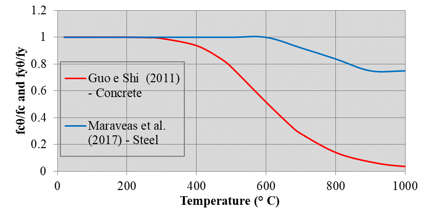
The elevation of the temperature in the steel causes reduction in its resistance. After cooling, steel may, under certain circumstances, recover its initial strength. Transformations in its crystallography, obtained at temperatures above the eutectic point (approximately 720 ° C), partially impede the recovery of the resistance, thus, there is a residual loss of resistance (Smith et al., 1981, apud SILVA et al., 2006). This reduction factor is presented in Figure 1. However, it is worth noting that the international literature presents several values for the reduction of the mechanical properties of the materials after fire and often with very divergent values. This demonstrates the need for more research to reach consensus.
This work aims to simulate experimentally the impact caused by a fire in reinforced concrete beams. Then, a numerical model developed in the ABAQUS finite element program will be presented in order to evaluate the residual mechanical strength of these beams. In this sense, it is expected to contribute to the procedure for evaluating reinforced concrete structures after fires, presenting a valid strategy for this purpose.
EXPERIMENTAL MODEL
The experimental program developed in this research was carried out at the Structural and Materials Laboratory of the Civil Engineering Department of the Federal University of Pernambuco and the Francisco Adrissi Ximenes Aguiar Technical School (SENAI - FAXA), in the municipality of Cabo de Santo Agostinho - PE.
In the experimental program, 12 reinforced concrete beams with a length of 1.20 m and cross section of 0.12 mx0.20m, representing the base and the height respectively, were tested. The compressive strength of the concrete after 60 days is fc = 47.6 MPa and was determined, by arithmetic mean, through 4 cylindrical specimens measuring 0.10 m x 0.20 m.
The concrete was dosed and had the characteristics shown in Table 1.
| Description | Value |
| Cement CP II F32 | 837 kg |
| White Sand - Throw | 1809 kg |
| Average sand | 603 kg |
| Brita 25mm | 3741 kg |
| Water | 456 l |
| MBT 61R Handlebar Retractor | 2.637 l |
| Mass Trace (cement : sand : gravel) | 1: 2.88: 4.47 |
| Water / cement factor | 0.54 |
| Compressive strength at 28 days of design (fck) | 30 MPa |
| Slump | 60 ± 10mm |
| Mean compressive strength at test time (60 days) | 47.6 MPa |
| Mass Humidity | 4.4% |
| Dry Density | 2400 kg / m³ |
For positive longitudinal reinforcement, two bars ϕ = 10mm, CA-50 steel, were employed and for transverse reinforcement, bars of ϕt = 6.3mm, CA-60 steel were used, with spacing close to the supports of 60 mm and 80mm in the central region of the beam. In the upper part of the beam, 2 bars ϕm = 6.3 mm, Steel CA-60, were used as mounting reinforcement, only with the stirrup holder function. The concrete cover c1 (distance between the face and the longitudinal reinforcement axis), according to NBR 15200:2012, was 30 mm
For positive longitudinal reinforcement, two bars ϕ = 10mm, CA-50 steel, were employed and for transverse reinforcement, bars of ϕt = 6.3mm, CA-60 steel were used, with spacing close to the supports of 60 mm and 80mm in the central region of the beam. In the upper part of the beam, 2 bars ϕm = 6.3 mm, Steel CA-60, were used as mounting reinforcement, only with the stirrup holder function. The concrete cover c1 (distance between the face and the longitudinal reinforcement axis), according to NBR 15200:2012, was 30 mm.
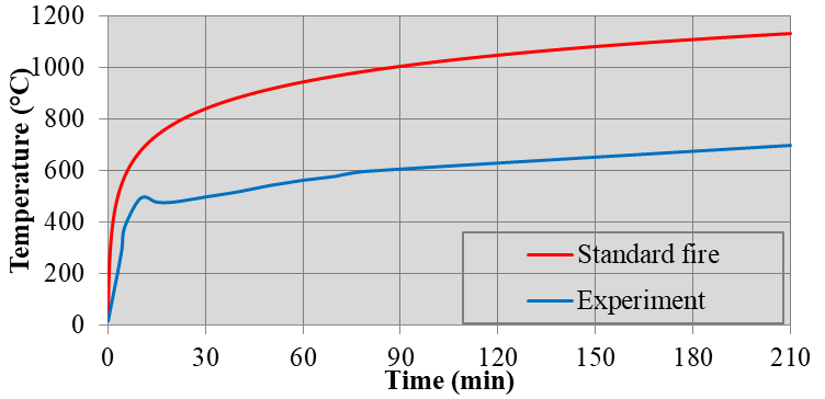
The assay was performed after 60 days of sample curing and consists of two steps. First, the heating of the beams, according to the curve of Figure 2. In this step, there is no application of mechanical load. Then, after 24 hours, time for the cooling, the mechanical load was applied until the rupture, according to the model of Figure 4 (c).
Three beams were tested at room temperature, that is, without heating to determine the reduction of residual resistance.
The heating of the beams, without application of mechanical load, took place in three batteries of fire tests with durations of 60 min., 120 min. and 210 min., corresponding to the programmable limits of the furnace used, with three samples (beams) for each battery. The heating curve is shown in Figure 2.
Due to the limitation of the furnace employed, the standard fire curve (NBR 15200:2012) could not be adopted. For comparison purposes, this curve is also represented in Figure 2.
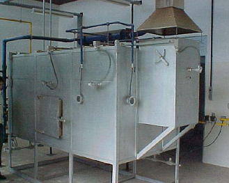
In table 2 the characteristics of the furnace used for fire exposition of the beams at elevated temperatures are presented. Figure 3 shows the photo of this furnace.
| Furnace characteristics | |
| External dimensions | 2.6x2.35 x 1.6 m |
| Internal dimensions | 2.1x1.00 x 1.00 m |
| Burner power used | 402,000 kcal / h |
| Fuel | Natural gas |
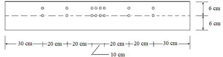
The beams were exposed to fire in 3 faces, considering the worst situation in a fire situation. The compressed face of the beam was insulated with the ceramic fiber blanket (insulation material) inside the furnace, as shown in Figure 4 (b), to ensure that the top of the beam was not heated by conduction. The temperatures inside the structural part and the gases inside the furnace were monitored by 20 K-type thermocouples: 16 of them were placed along the beam, as shown in Figure 5, and 4 thermocouples located on the top of the furnace.
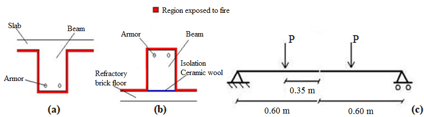
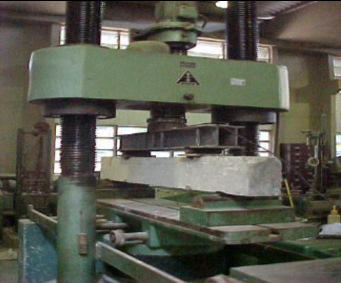
The mechanical test of the beams occurred after cooling to room temperature. The load was applied by a hydraulic press whose maximum load capacity was 3000 kN, according to Figure 6. Throughout the mechanical test the mechanical load applied to the beam was recorded by 300 kN load cells. The test scheme is shown in Figure 4 (c) where the beams were loaded until rupture. The load application rate was 1 kN /s.
NUMERICAL MODEL
Geometric Properties of Beams
In this work, the three-dimensional, non-linear numerical model for finite element analysis of reinforced concrete beams was developed in the ABAQUS / Standard program (2013).
The geometric properties of the model follow strictly what is described in the experimental program.
Type of Finite Element
The ABAQUS library has a variety of finite elements of different types such as Solids, Shell, Membrane, Frame, among others.
In this study, in the thermal analysis, two types of finite elements were used for discretization of the respective beams, being:
DC3D8, being the same 3D, of linear formation and composed of 8 nodes, for concrete and longitudinal reinforcement;
DC1D2, element 1D, that is, link, with linear formation and composed of 2 nodes, used in the transverse reinforcement.
For mechanical analysis, the following elements were adopted:
C3D20R, solid type element, used in the discretization of the concrete. It is a continuous element (C), three-dimensional (3D), with twenty nodes (20), reduced integration and has the option hourglass control, which allows to improve the resolution of problems related to obtaining oscillatory solutions, exhibiting spurious modes, that is, when the matrix becomes singular or almost singular (when the matrix does not admit inverse). It presents quadratic formation and three degrees of freedom of translation at each node;
C3D6, a solid type element used in the discretization of the longitudinal reinforcement. It is a continuous element (C), three-dimensional (3D) and with six nodes (6).
T3D2, lattice element that has two nodes, presenting three degrees of freedom per node, referring to the translations in the x, y and z directions. This element was used in the discretization of the transverse reinforcement.
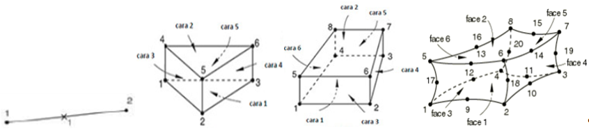
Figure 7 illustrates the types of elements used in the numerical model.
Finite Element Mesh
The reinforced concrete beams were discretized in the thermal analysis in elements of 10 mm x 10 mm x 10 mm for concrete, 20 mm x 20 mm x 20 mm for longitudinal reinforcement and 20 mm for transverse reinforcement. For mechanical analysis, meshes of 50 mm x 50 mm x 50 mm for the concrete, 40 mm x 40 mm x 40 mm for the longitudinal reinforcement and 20 mm for the transverse reinforcement were discretized.
For each analysis, thermal and mechanical, approximately 49066 and 2514 elements were generated, connected by 56808 and 9907 nodes, respectively. It was verified that there would be no significant improvement in the results with more refined meshes.
Properties of Materials
For the numerical analysis, thermal and mechanical properties for the materials of reinforced concrete beams were adopted according to national standards NBR 6118 (2014), NBR15200 (2012) and NBR14323 (2013).
For thermal analysis it is necessary to define the specific mass, coefficient of thermal expansion, thermal conductivity and specific heat for concrete and steel as a function of temperature. The specific mass was considered constant, with values equal to 7850 kg/m³ and 2400 kg/m³ for steel and concrete, respectively.
For mechanical analysis it is necessary to define the modulus of elasticity, Poisson coefficient and the plastic properties of the materials as a function of temperature.
When it is considered that the structure will undergo finite deformations, the tensions (σ) and deformations (ε) must be considered based on the actual geometry of the deformed structure. The true values are given by equations (1) and (2).
In ABAQUS the plastic behavior of the material defined by these measurements is considered, with the true tension related to the plastic part of the true deformation (SILVA, 2006).
The mechanical properties of the materials at room temperature were obtained through experimental tests: compressive strength of 47.6 MPa for the concrete; and flow stresses of 500 MPa and 600 MPa for the steel used in longitudinal bars and transverse bars reinforcements, respectively. The modulus of elasticity adopted for the steel was 210 GPa.
In order to determine the residual value of the mechanical properties, the coefficients proposed by Guo and Shi (2011) and Maraveas et al. (2017), respectively, for concrete and steel, since these values are commonly employed in similar studies.
The Poisson coefficient can also be considered constant, and so the values adopted were 0.3 and 0.2, respectively, for steel and concrete.
Contour Conditions, Loading and Contact
To simulate the thermal action in the numerical model, two types of surfaces, around the beam subjected to high temperatures, were used, namely, film condition and radiation, which represent, respectively, the phenomena of heat transfer by convection and radiation. It should also be noted that the value of 0.95 for the emissivity of the concrete was considered. The value of 25 W/m² was adopted for the heat transfer coefficient by convection.
For the thermal analysis, the contact between concrete and longitudinal and transverse reinforcements were modeled with Tie behavior, simulating the perfect contact, so that there was no loss of heat.
In the mechanical model, the contact between the concrete and the reinforcements was made by the Embedded region function, in order to guarantee a perfect solidarity between the materials, according to the fundamental hypothesis of the reinforced concrete theory.
The numerical model represented bi-supported condition for the beans used in experiments, with span of 1.20m (Figure 8).
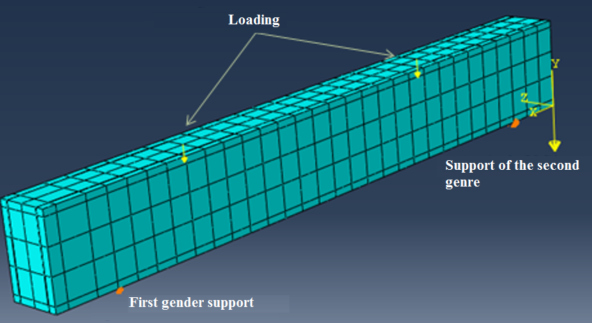
Following the experiment, two equal concentrated loads were applied to the upper face of the beam, equidistant from the middle of the span, that is, 0.35 m, with a velocity of 1 kN /s, according to Figure 4 (c). The auxiliary command constraint coupling, located in the interaction menu in ABAQUS, which has the function of avoiding the concentration of efforts at the point of application of the concentrated load, was also used. In addition to these loads the weight of the beam was also considered.
Finally, it is emphasized that the geometric nonlinearity parameter was activated (* NLGEOM = ON), so that the effect of large displacements was considered.
NUMERICAL AND EXPERIMENTAL RESULTS
Temperature analysis
In this section, the temperatures results of the concrete beam recorded during the experiments and those obtained from the numerical model are compared.
Figures 9, 10 and 11 (a) shows these results at the beam cross section. The point chosen for comparison is shown in Figures 9, 10 and 11 (b), in red. At this point thermocouples were positioned in the experiment, facilitating this comparison. The temperature gradient in the concrete section is obtained through the numerical results and is represented in the same Figures 9, 10 e 11 (b).
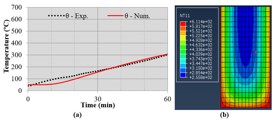
In the three test batteries, i.e. 60 min., 120 min. and 210 min, the experimental and numerical temperatures for the concrete presented very close values, evidencing a strong correlation between these results (Figures 9, 10 and 11). Some divergence is observed for temperatures around 100ºC. This difference can be attributed to the movement of water vapor inside the concrete and not faithfully represented in this numerical model. For this, it is necessary to develop a thermo - hydraulic - mechanical model for this analysis.
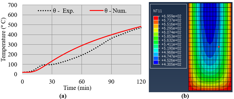
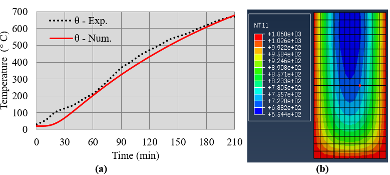
It is evident the low conductivity of the concrete generating high temperature gradients (Figures 9, 10 and 11). This gradient may contribute to the occurrence of spalling, specially at the corners of the cross section. However, in the experimental test there was no spalling, probably because it was a concrete not dense enough (fc = 47.6 MPa) and low humidity (4.4%).
On the other hand, the low conductivity of the concrete slows down the temperature increase in the region of the steel bars and the inner core of the concrete, allowing it to retain its resistance, and consequently, to perform better in the fire.
It is noteworthy that near 100 °C, temperature growth curves presented a short period of time (around 10 minutes) without significant increase. This is a result of the change of state of free water existing in the parts. This phenomenon was also observed in specimens from previous experiments, as reported by Kalifa et al. (2000). As previously mentioned, in this section the numerical model does not faithfully follow this behavior, but nevertheless, it presents an acceptable approximation of the results, i.e., maximum difference lower than 50 ºC.
Thus, it can be concluded that the numerical model was able to represent the temperature distribution in the reinforced concrete beams with results very close to those recorded experimentally.
Mechanical analysis
This section presents the value of residual strength after cooling of the concrete beams tested, as well as this value obtained by the numerical analysis.
In order to allow the comparison between the loads obtained numerically and experimentally, the value of the vertical displacement in the middle of the span (arrow) for the maximum load supported by the beam was adopted as failure criterion. This value was defined according to the expression recommended by NBR 6118 (2014) for cracked concrete structures as a function of the load of rupture applied to the beam.
Table 3 presents the comparison of the load of rupture of the reinforced concrete beams obtained in the experimental program and through the numerical model.
| Experiment | Arrow on half goes (mm) | Experimental Breakdown Load (kN) | Numerical Breakdown Load (kN) | Error (%) |
| Environment | 5.3 | 78.6 | 74.5 | 5.2 |
| 60 min. | 5.2 | 77.2 | 73.5 | 4.9 |
| 120 min. | 5.2 | 75.6 | 70.8 | 6.4 |
| 210 min. | 3.7 | 47.6 | 44.9 | 5.7 |
The times of 60 min and 120 min of fire exposure were not sufficient to significantly reduce the residual strength of the reinforced concrete beam. It is observed that the temperatures developed in the section were not high enough to cause a degradation of the constituent materials up to 120 min. of fire exposure. This shows the good performance of the reinforced concrete structures when subjected to fires. However, the heating of 210min caused a considerable reduction in the residual resistance; the load of rupture in this situation was of 47.6 kN, that means, 60% of the maximum load capacity at ambient temperature (Table 3).
Finally, it was observed that all numerical results had a very similar tendency to those obtained experimentally, with errors less than 7% in determining the load of rupture of the beams of reinforced concrete. In this way the model is valid and accurate enough to predict the residual structural behavior of reinforced concrete beams submitted to pure bending after fire.
CONCLUSIONS
This work presented an experimental program to determine the residual strength of reinforced concrete beams after a fire. In addition, a numerical, non-linear numerical model developed in finite elements capable of simulating the thermal and mechanical behavior of this type of structural element was presented. Based on these results the following can be highlighted:
The reinforced concrete beams presented a good residual performance after fire, resisting to 120 min without loss of resistance;
The numerical approach developed for thermal analysis produced quite satisfactory results when compared with those obtained experimentally;
The numerical approach developed for residual mechanical analysis produced accurate results with errors lower than 7% when compared to the experiment;
The numerical model presented can be used to predict the thermal and mechanical (residual) behavior of reinforced concrete beams bi-supported after the fire;
REFERENCES
ABAQUS/CAE (2013), “Standard User’s Manual, version 6.13”, Simulia Corp., USA,
Associação Brasileira de Normas Técnicas (2014), “NBR-6118: Projeto de Estruturas de Concreto”. Rio de Janeiro.
Associação Brasileira de Normas Técnicas (2013), “NBR-14323: Projeto de estruturas de aço e de estruturas mistas de aço e concreto de edifícios em situação de incêndio - procedimento”. Rio de Janeiro.
Associação Brasileira de Normas Técnicas (2012), “NBR-15200: Projeto de estruturas de concreto em situação deincêndio”. Rio de Janeiro.
Corrêa, C., Rêgo Silva, J. J., Pires, T. A., Braga, G. C. (2015), “Mapeamento de Incêndios em Edificações: Um estudo de caso na cidade do Recife”. Revista de Engenharia Civil IMED, V. 2, Nº. 3, 2015. https://doi.org/10.18256/2358-6508/rec-imed.v2n3p15-34
International Organization for Standardization (1999), “ISO 834 Fire-resistence tests – Elements of building construction – Part 1: General requirements”.
Guo, Z., Shi, X. (2011), “Experiment and calculation of reinforced concrete at elevated temperatures”. Elsevier, eBook ISBN: 9780123869630, 336p.
Kalifa, P. et al. “Spalling and pore pressure in HPC at high temperatures” (2000). Cemente and concrete Research nº 30. 1915-1927. https://doi.org/10.1016/S0008-8846(00)00384-7
Maraveas, C., Fasoulakis, Z., Tsavdaridis, K. D. (2017), "Post-fire assessment and resinstatement of stell structures". Journal of structural fire engineering, v. 8, n. 2, p. 181-201. https://doi.org/10.1108/JSFE-03-2017-0028
Morales, G., Campos, A., Fagarello, A. M. P. (2011), “The action of the fire on the components of the concrete”. Semina: Ciências Exatas e Tecnológicas, Londrina, v. 32, n. 1, p. 47-55, jan. /mar. DOI: 10.5433/1679-0375.2011v32n1p47
Neville, A. M. (1997), “Propriedades do concreto”. 2ª ed, Pini.
Pires, T. A. (2007), “Gerenciamento de riscos de incêndio: Avaliação do impacto em estruturas de concreto armado através de uma análise experimental de vigas isostáticas”. Dissertação de mestrado. Universidade Federal de Pernambuco
Pires, T. A., Rodrigues, J. P. C., e Silva, J. J. R. (2012), “Fire resistance of concrete filled circular hollow columns with restrained termalelongation.”, Journal of Constructional Steel Research, v. 77, pp. 82-94.https://doi.org/10.1016/j.jcsr.2012.03.028
Rodriguez, G., Bonilla, J., Hernandez, J. (2016), Modelación numérica de vigas continuas de gran peralto de hormigón armado. Revista Ingeniería de Construcción, 2016, vol.31, n.3, p. 163-174. http://dx.doi.org/10.4067/S0718-50732016000300002
Santiago Filho, H. A., Pereira, R. G., Pires. T. A., et. al. (2017), “Analysis of a reinforced concrete slab in a fire situation”. Anais 59º IBRACON – Congresso brasileiro do concreto.
Smith, C. I., Kirby B. R., Lapwood, D. G., Cole, K. J., Cunningham, A. P., Preston, R. R. (1981), “The Reinstatement of Fire Damaged Steel Framed Structures” Fire Safety Journal, 4 p. 21-62. https://doi.org/10.1016/0379-7112(81)90004-7
Silva A. L. R. C. (2006), “Análise numérica não-linear da flambagem local de perfis de aço estrutural submetidos à compressão uniaxial”, Tese de Doutoramento em Engenharia de Estruturas, Escola de Engenharia da Universidade Federal de Minas Gerais, p. 205,
Silva, V. P., Fakury, R. H., Rodrigues, F. C., Pannoni, F. D. (2006), “A real fire in small apartment – a case study”. Anais do 4th structures in fire. Aveiro.
Silva, V. P. (2012), “Projeto de estruturas de concreto em situação de incêndio: conforme ABNT NBR 15200:2012”. São Paulo, Blucher.
Author notes
tacpires@yahoo.com.br
Additional information
Cite as: R. G. Pereira, T. A. Carvalho Pires, D. Duarte, J. J. Rêgo Silva (2019), "Assess of residual mechanical resistance of reinforced concrete beams after fire", Revista ALCONPAT, 9 (1), pp. 93 – 105, DOI:
http://dx.doi.org/10.21041/ra.v9i1.299
Legal Information: Revista ALCONPAT is a quarterly publication by the Asociación Latinoamericana de Control de Calidad,
Patología y Recuperación de la Construcción, Internacional, A.C., Km. 6 antigua
carretera a Progreso, Mérida, Yucatán, 97310, Tel.5219997385893, alconpat.int@gmail.com,
Website: www.alconpat.org
Responsible editor: Pedro
Castro Borges, Ph.D. Reservation of rights for exclusive use
No.04-2013-011717330300-203, and ISSN 2007-6835, both granted by the Instituto
Nacional de Derecho de Autor. Responsible for the last update of this issue,
Informatics Unit ALCONPAT, Elizabeth Sabido Maldonado, Km. 6, antigua carretera a Progreso, Mérida, Yucatán, C.P. 97310.
The views of the authors do
not necessarily reflect the position of the editor.
The total or partial
reproduction of the contents and images of the publication is strictly
prohibited without the previous authorization of ALCONPAT Internacional
A.C.
Any dispute, including the
replies of the authors, will be published in the third issue of 2019 provided
that the information is received before the closing of the second issue of 2019.