Network of Scientific Journals from Latin America and the Caribbean, Spain and Portugal
Service life analysis of reinforced concrete structure under uniform corrosion through ANN model coupled to the FEM
Análisis da vida útil de estructuras de concreto armado bajo la acción de la corrosión uniforme por medio de un modelo con RNA acoplado al MEF
Análise da vida útil de estruturas de concreto armado sob corrosão uniforme por meio de um modelo com RNA acoplado ao MEF
Service life analysis of reinforced concrete structure under uniform corrosion through ANN model coupled to the FEM
Revista de la Asociación Latinoamericana de Control de Calidad, Patología y Recuperación de la Construcción, vol. 8, no. 1, 2018
Asociación Latinoamericana de Control de Calidad, Patología y Recuperación de la Construcción, A. C.
Received: 24 August 2017
Accepted: 18 December 2017
Published: 31 January 2018
Abstract: The present work intends to analyze and numerically model the corrosion process, estimating the service life of concrete structures. The modelling process was divided in two stages, initiation and propagation. The modeling of the initiation phase was carried out by Artificial Neural Networks (ANN), and the modeling of the propagation phase was done by means of Finite Element Method (FEM). The results show the efficiency of the model generated by the coupling of ANN to the FEM to analyze and study the durability of reinforced concrete structures under uniform corrosion, and the numerical model applicability to estimate the service life of reinforced concrete structures.
Keywords: reinforced concrete, reinforcement corrosion, service life, Artificial Neural Networks, Finite Element Method.
Resumen: Este estudio tiene como objetivo analizar y estimar la vida útil de estructuras de hormigón armado bajo la acción de corrosión uniforme. El modelado se dividió en dos etapas, iniciación y propagación. El modelado de la fase de iniciación fue realizado por medio de Redes Neuronales Artificiales (RNA) y el modelado de la fase de propagación fue hecho por medio del Método de los Elementos Finitos (MEF). El acoplamiento de la RNA en el MEF posibilitó analizar y estudiar la durabilidad de estructuras de hormigón armado bajo la acción de corrosión uniforme, presentándose como una metodología alternativa para la estimación del tiempo de vida útil de estas estructuras.
Palabras clave: hormigón armado, corrosión de las armaduras, vida útil, Redes Neuronales Artificiales, Método de los Elementos Finitos.
Resumo: O presente trabalho apresenta uma análise numérica da vida útil de estruturas de concreto armado sujeitas à corrosão uniforme. O processo de modelagem foi dividido em dois estágios, iniciação e propagação. A modelagem da fase de iniciação foi feita via Redes Neurais Artificiais (RNA) enquanto que a fase de propagação foi modelada através do Método dos Elementos Finitos (MEF). Os resultados demonstram que o modelo gerado pelo acoplamento das RNA ao MEF, possibilita de forma eficiente, a simulação da degradação de estruturas de concreto armado devido à ação da corrosão uniforme e, a aplicabilidade da ferramenta numérica quanto a previsão da vida útil destas estruturas.
Palavras-chave: concreto armado, corrosão de armaduras, vida útil, Redes Neurais Artificiais, Método dos Elementos Finitos.
1. INTRODUCTION
Among the factors for the sustainable development and economic growth of modern society are the reliability and durability of structures and infrastructure facilities, especially reinforced concrete structures. However, such structural systems are vulnerable to deterioration processes resulting from chemical degradation and physical damage, which, over time, can lead to unsatisfying structural performance under service loads or accidental actions.
In the last years, there have been significant advances in modeling, analysis and design areas relate to the deterioration in structures, besides as new approaches have been proposed to evaluate the service life of structures (Ellingwood, 2016; Biondini et al., 2017, Andrade et al., 2017).
The corrosion of reinforcement is the pathological manifestation with the highest occurrence rate in reinforced concrete structures (Kari et al., 2014). In Brazil, for example, this rate varies from 14 to 64% depending on analysis zone (Carmona et al., 1988; Dal Molin, 1988; Andrade, 1992).
A precise and computationally efficient structural modeling of corrosion deterioration is an essential for structural reliability and service life analysis in order to reduce the maintenance costs of structures; especially reinforced concrete structures (Vu et al., 2000, Rao et al., 2017).
Corrosion of steel reinforcement in concrete is an electrochemical process caused by differences in the concentrations of dissolved ions, so that part of the metal becomes cathodic and another anodic, resulting in the loss of material volume and the formation of corrosion products, which is a secondary material with a volume of 3 to 10 times greater than the initial one (Mehta et al., 2014; Geiker et al., 2016).
Concrete damage modeling due to uniform corrosion has been used phenomenological processes that segment and synthesize steel corrosion, immersed in reinforced concrete, in two stages, initiation and propagation.
The initiation phase corresponds to the period that the transport of aggressive agents (CO2) occurs in the porous matrix of concrete, resulting in reducing the pH (from approximately 12.5 to 8.5) and in the depassivation of steel reinforcement. Conversely, the propagation phase is characterized by the loss of steel mass and the formation of corrosion products, which causes cracking of concrete cover or, in advanced stages, the concrete spalling (Tuutti, 1982; Bakker, 1988; Rao et al. al., 2017).
The projects costs of reinforced concrete structures that consider only the initiation period for corrosion are not the most economical, precisely because they do not consider the maintenance costs caused during the corrosion propagation, an important consideration in the service life analysis of reinforced concrete structures (Yanaka et al., 2016).
Given the above, this work analyzes the service life of reinforced concrete structures through the coupling of two models, one responsible for the time estimation at which occurs the steel depassivation (design life - DL) and another referring to the time at which the concrete element reaches the serviceability limit state (service life - SL).
2. SERVICE LIFE OF CONCRETE STRUCTURES UNDER CORROSION
The service life, safety, reliability and risk of civil infrastructure systems have become emerging problems in recent years due to natural and human disasters, sustainability issues and global warming.
The durability management of civil infrastructure involves significant expenses and, in an era of limited public resources, requires difficult decisions to establish maintenance, rehabilitation, and replacement priorities. In this regard, the definition of service life stands out as an important concept, which serves as the basis for a holistic design approach. Structures should be designed for structural safety and maintenance for a specified period, which includes a design for durability and sustainability. With the aim of design a structure with a low-maintenance during its service life, measures must be taken in the early stages of design, and it is necessary to carry out the control during the structure service life (Ellingwood et al., 2016).
Corrosion is one of the main causes of reduced service life of reinforced concrete structures, since this involves the material loss from steel surface as a result of a chemical action. The material loss leads to an effective area reduction of cross section, and, consequently, decreased load-bearing capacity.
However, corrosion can be delayed by adopting a medium or high durability concrete (depending on the exposure environment) or by considering a suitable thickness for the concrete cover. Broomfield (2007) and Dyer (2015) report that the lower the concrete cover and quality, the greater the corrosion possibility and, consequently, its degradative effects, e.g., the cracking in concrete.
The concrete alkalinity is due to the high concentrations of soluble calcium, sodium and potassium oxides present in the concrete microscopic pores. These oxides form hydroxides, alkaline in the presence of water, creating an optimal pH condition (between 12 and 13). In this way, the concrete protects the steel from corrosion both physically by forming a protective layer for the reinforcement, and chemically through of the alkaline condition that induces the formation of a passive film on the steel surface, very dense, thin layer of oxide, and leading to a very slow rate of corrosion (Broomfield, 2007; Köliö et al., 2017).
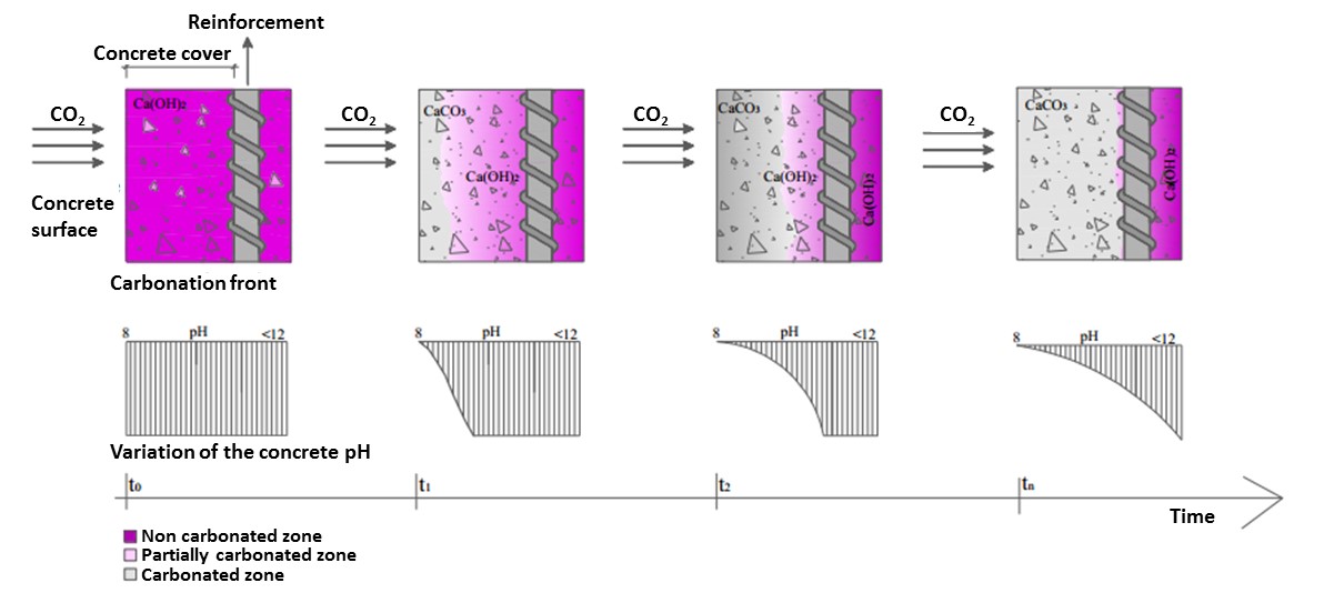
The uniform corrosion process, carbonation corrosion, can be segmented into two phases, initiation and propagation. The diffusion process of CO2 characterizes the initiation phase. Carbon dioxide enters the concrete porous matrix reacting with the calcium hydroxides (Ca(OH)2) present in the cement paste, leading to the formation of calcium carbonate (CaCO3) (Figure 1). In the literature, this process is called carbonation, and is responsible for some alterations in carbonated concrete, e.g., permeability reduction (Neville, 1997). In addition, this process reduces the pH of concrete (approximately 12.5 to 8.5), resulting in the destruction of a chemical layer that protects steel from corrosion mechanisms (Chang et al., 2006) (Figure 1).
The carbonation reaction begins at the concrete surface progressing internally over time. As the carbonation front reaches the steel depth, the corrosion progression phase begins, with no actual damage to the structure to this point (Tuutti, 1982; Possan, 2010; Köliö et al., 2017).
In the propagation stage, for the corrosion products formation, it is necessary, firstly, the transformation of ferrous hydroxide into ferric hydroxide (1), and then, the transformation into hydrated ferric oxide, also called the corrosion product (2).
Propagation is determined by the corrosion rate (governed by oxygen availability, relative humidity and temperature) and by the capacity of concrete cover to withstand internal stresses. The unhydrated ferric oxide (Fe2O3) has a volume of about twice that of steel it replaces when fully dense. Ferric oxide upon hydration expands further, becoming porous, increasing the volume at the steel-concrete interface about six to ten times, and causing loss of effective steel area.
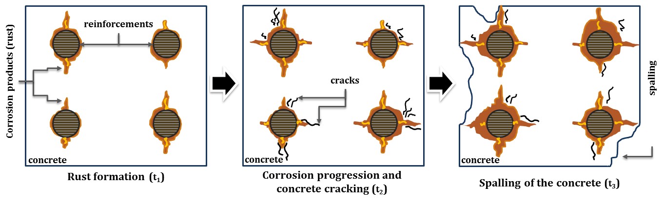
The concrete expansion due to formation of corrosion products results in the cracking of concrete cover, this occurs when the stresses induced by the increasing layer of corrosion products exceed the tensile strength capacity of concrete, especially in structures with low concrete covers. The cracking in concrete facilitates and accelerates the diffusion of external agents, and may cause greater damages to the concrete, e.g., the concrete spalling (Figure 2), where a whole segment of concrete cover detaches from the structure surface. (Broomfield, 2007; Köliö et al., 2017).
3. CONCRETE STRUCTURES SERVICE LIFE
3.1 Description of the implemented model for the service life analysis
In order to determine the service life of reinforced concrete structures subjected to uniform corrosion, a FORTRAN code was developed. The code possibilities the geometric non-linear structure analysis of two-dimensional fibers composites solid based on the Positional Finite Element Method (PFEM) described in Coda (2003). To represent and simulate the effects and damages from the uniform corrosion propagation phase, an adaptation was made in the code, where the useful steel area of the reinforcement is actualized in function of the corrosion time progression as given in (3) and (4).
where is the service steel reinforcement (mm) in function of the corrosion progression time (years), is the initial bar diameter (mm), η is the rate corrosion (µA/cm²), w/c is the water/cement ratio and cob is the concrete cover (mm).
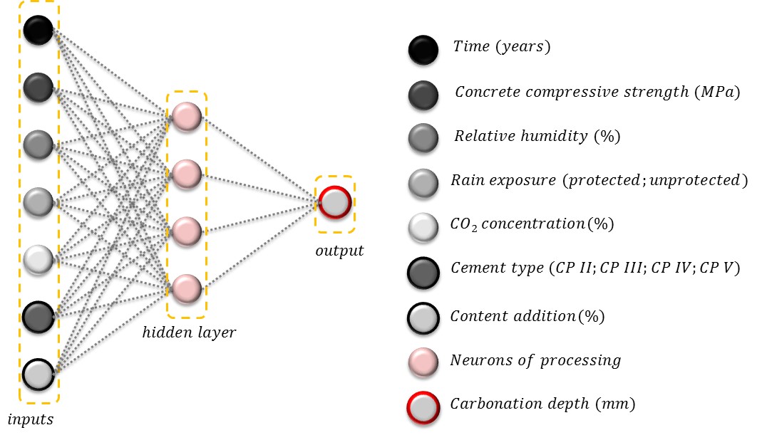
To determine when occur the steel reinforcement depassivation (referent to the DL), a concrete carbonation depth predictive model based on Artificial Neural Network Model (ANN) and developed by Felix (2016), was coupled to the PFEM code. The Figure 3 present the model inputs and the ANN topology (the neural architecture) utilized to developed the concrete carbonation model.
The time corresponding to the service life (SL) was determined in this work as the instant of time in which the characteristic crack width (5) is greater than the value described on NBR 6118 (ABNT, 2014) or the maximum vertical beam displacement is greater than 250/beam length, also described on NBR 6118 (ABNT, 2014).
where w is the characteristic crack width (mm), is the bar diameter (mm), is the surface conformation coefficient of the bar (1.0 to steel plain bar, 1.4 to steel notched bar e 2.5 to steel ribbed bar), is the tensile stress (kN/cm²), is the steel elasticity modulus (kN/cm²), is the concrete mean tensile (kN/cm²) e is the reinforcement ratio in relation to the surrounding concrete area.
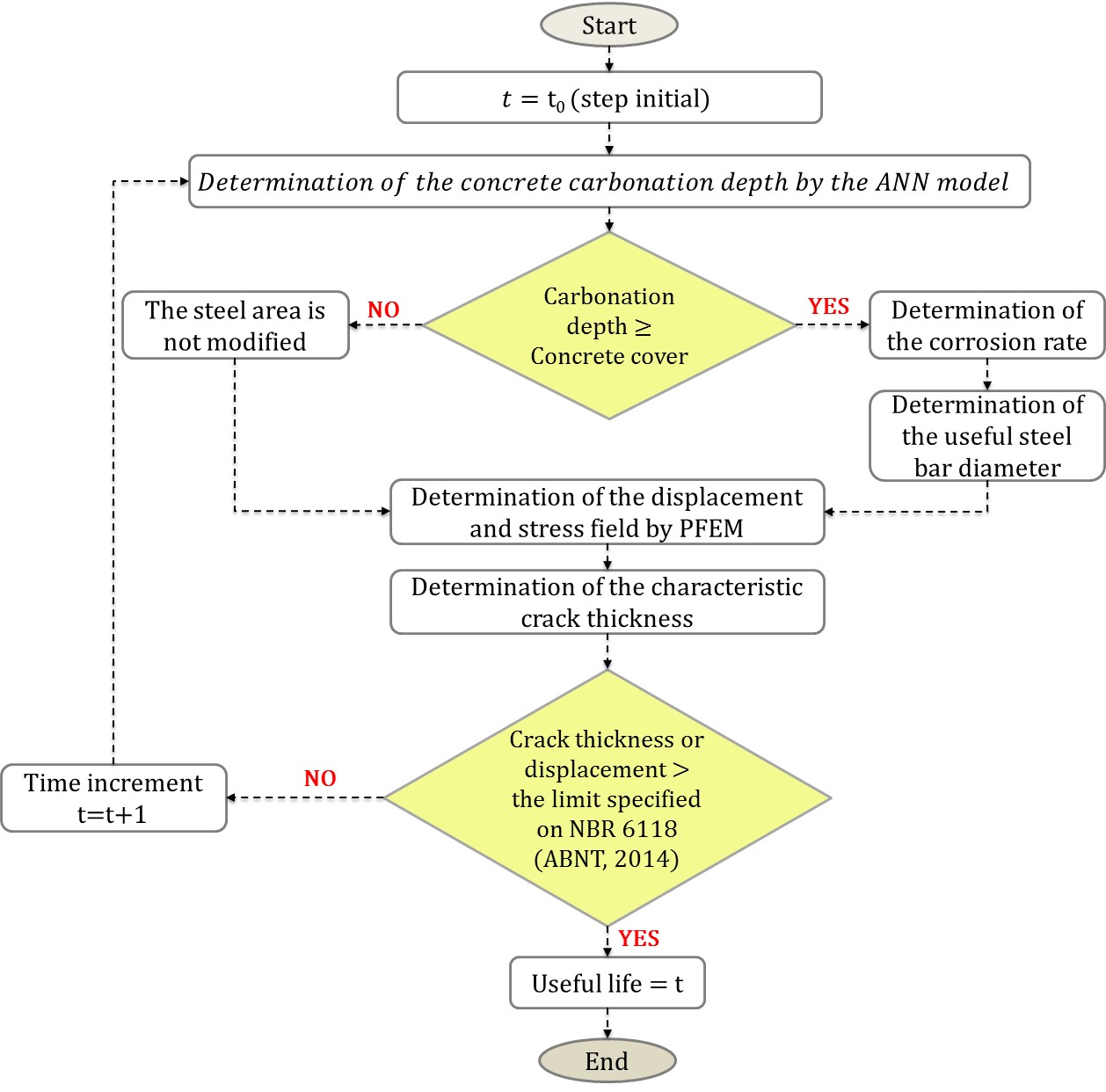
The Figure 4 show the flowchart referent to the model code implemented to determine the service life of reinforced concrete structures subjected to the uniform.
3.2 Validation of the concrete carbonation depth predicting model
The Figure 5a, 5b, 5c and 5d presents the concrete carbonation depth in function of the time for concrete structures in four different environment conditions (sceneries). The environment conditions are detail in the Table 1. With the purpose to demonstrate the model applicability and accuracy, the results obtained by the model were compared to different analytical models (Smolczyk, 1969; Vesikari, 1988; Bob et al., 1993; EHE, 2008; Possan, 2010) and real data Mehta (2014). More details about the analytical and the numerical model can be obtained in Felix (2016).
| Scenery | CO2 concentration (%) | Relative humidity (%) | Rain exposure | Cement type | Compressive strength (MPa) |
| I | 0.04 | 70.00 | Protected | CP II – E | 30.00 |
| II | 0.04 | 70.00 | Protected | CP III | 40.00 |
| III | 0.04 | 65.00 | Unprotected | CP IV | 40.00 |
| IV | 0.04 | 65.00 | Unprotected | CP V | 40.00 |
OBS. In all scenarios the addition content is zero and the analysis time is 60 years.
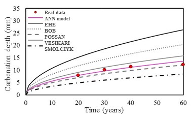
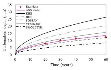
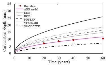
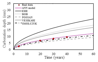
The results show the model applicability and that it presents as an efficient numerical tool to predict the carbonation concrete depth.
3.3 Validation of the reinforced concrete corrosion model
In order to validate the numerical model implemented and proposed in this work, a reinforced concrete beam subjected to the uniform corrosion was modeled, the results are compared with the experimental results obtained by Graeff (2007). The modeled structure consist in a reinforced concrete beam with a rectangular section. The beam dimensions is specified in the Figure 6.
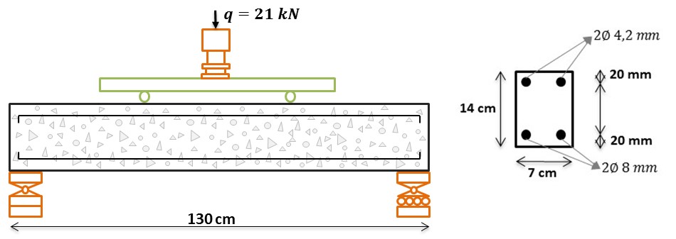
The concrete beam was discretized with two different mesh, where to represent the concrete matrix we used 134 triangular finite elements, and the reinforcements was represented with 120 simple bars elements.
Regarding the materials properties, the elasticity modulus of the concrete is 2600 kN/cm², the compressive strength is 2.5 kN/cm², the tensile strength adopted was 0.179 kN/cm² and the Poisson coefficient is 0.2. About the reinforcements, the elasticity modulus is 21000 kN/cm² and the tensile strength is 50 kN/cm². With the purpose to represent and modeling elastic-linear materials we used the Saint-Venant-Kirchhoff constitutive law.
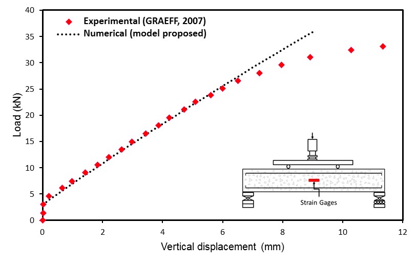
A comparison between the experimental, realized by Graeff (2007), and numerical (obtained with the model proposed) results of the vertical beam displacements is shown in the Figure 7. It is possible verified that the numerical model proposed represent efficiently the beam displacement field in the elastic linear regime of the material.
With the purpose to verify the applicability of the model to the determination of the effects caused by corrosion to reinforced concrete structures, the rate of increase of the vertical displacement of the center of the beam was compared as the reinforcement suffered degradation (loss of area), with the one obtained numerically by Graeff (2007).
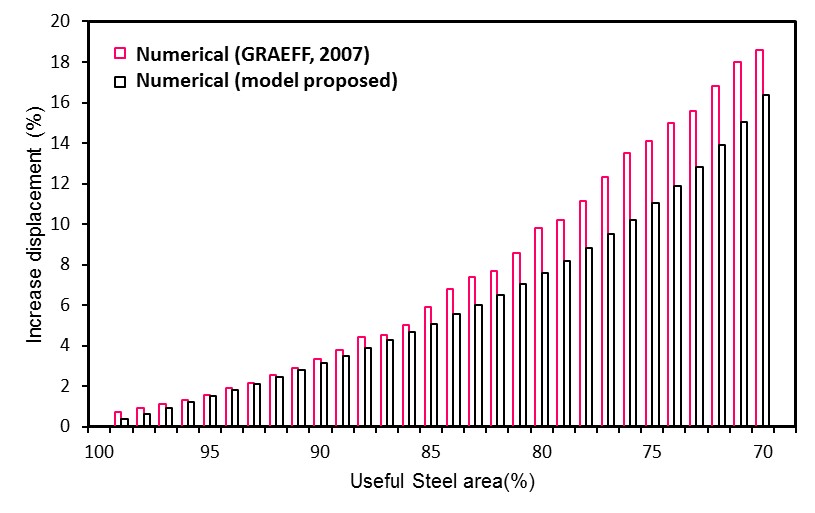
It is observed in Figure 8, that the difference between the responses of the two models is increasing with the evolution of the deformation of the armature, this is due to Graeff (2007) adopting in its model a nonlinear constitutive law. However, the model proposed in this work obtains displacements equivalent to the Graeff (2007), presenting 3.20% of average deviation.
3.4 Description of the analyzed structure
The structure analyzed in this work consists of a reinforced concrete beam dimensioned according to the procedures of NBR 6118 (ABNT, 2014). The Figure 9 present the values of the loads utilized to design the reinforced concrete beam and analyze the service life. In the Figure 9 the construction and geometric details have also shown. In order to analyze the concrete structure durability exposed to a moderately aggressiveness environment, the structure was dimensioned with three different concrete cover (i.e., 20, 25 and 30 mm).
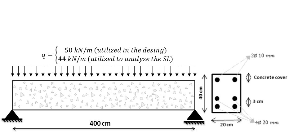
The concrete beam was discretized with two different mesh, where to represent the concrete matrix we used 486 triangular finite elements, and the reinforcements was represented with 900 simple bars elements. With the purpose to represent and modeling elastic-linear materials we used the Saint-Venant-Kirchhoff constitutive law.
The data relative to the properties of the materials are presented in Table 2(a), while in Table 2(b) the concrete and conditions exposure data are presented.
| Material | Property (kN/cm²) | Value |
| Concrete | Elasticity modulus | 2607.16 |
| Poisson coefficient | 0.20 | |
| Compressive strength | 3.00 | |
| Tensile strength | 0.21 | |
| Steel | Elasticity modulus | 21000.00 |
| Tensile strength | 50.00 |
| Attribute | Condition |
| Cement type | CP III |
| Content additions (%) | 0.00 |
| Relative humidity (%) | 60.00 |
| Rain exposure | Outdoor |
| CO2 concentration (%) | 0.04 (urban environment) |
4. RESULTS
Initially, the concrete carbonation depth advance and the design life (DL) of the beams with different cover thicknesses (20, 25 e 30 mm) are presented in Figure 10. It is immediately noticeable the importance of using an adequate concrete cover due to the aggressiveness of the medium to which the concrete structure is exposed, since adequate covering increases the DL and consequently the time required for the first human interventions and structural repairs.

In Figure 11 it is possible to analyze the advance of the degradation of the reinforcement due to the action of corrosion (the graph shows the steel area of the longitudinal reinforcement). It is observed that during the corrosion initiation phase (DL) the steel area of the reinforcement is not reduced, and the section loss is more pronounced in the early years of the corrosion propagation period, in agreement with the study of Vu et al. (2000). The authors report that there is a tendency of greater loss of steel area in the initial period of corrosion because the corrosion rate of the reinforcement is higher during this period, decreasing over time with an exponential behavior.

Figure 12 shows the DL of the reinforced concrete beams analyzed in this work. The crack width limit adopted was wlim = 0.3 mm, as prescribed by NBR 6118 (ABNT, 2014) for concrete structures with class II of environmental aggression (moderate).

It is observed that the slope of the crack opening curve decreases with the increase of the concrete cover, increasing the time required for the reinforced concrete structure to reach the cracking-opening limit state (relative to the SL).
Finally, Figures 13, 14 and 15 show the longitudinal tensions and vertical displacements of the reinforced concrete beam with 20, 25 and 30 mm of concrete cover, at the moment the cracks reach their limit value (DL).
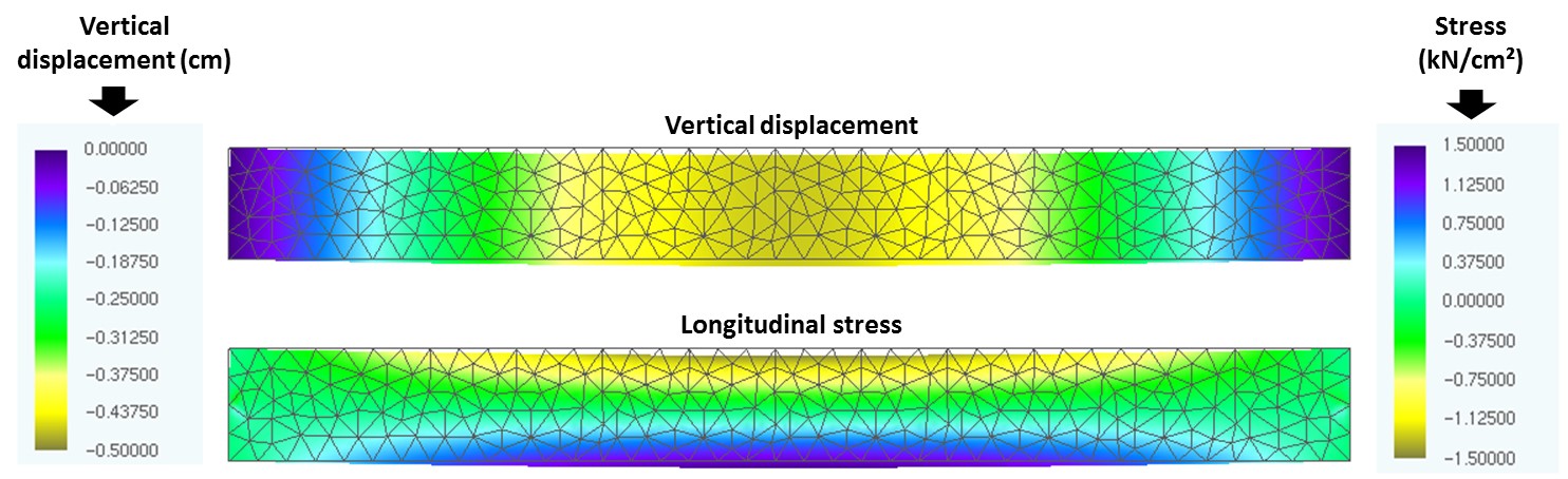
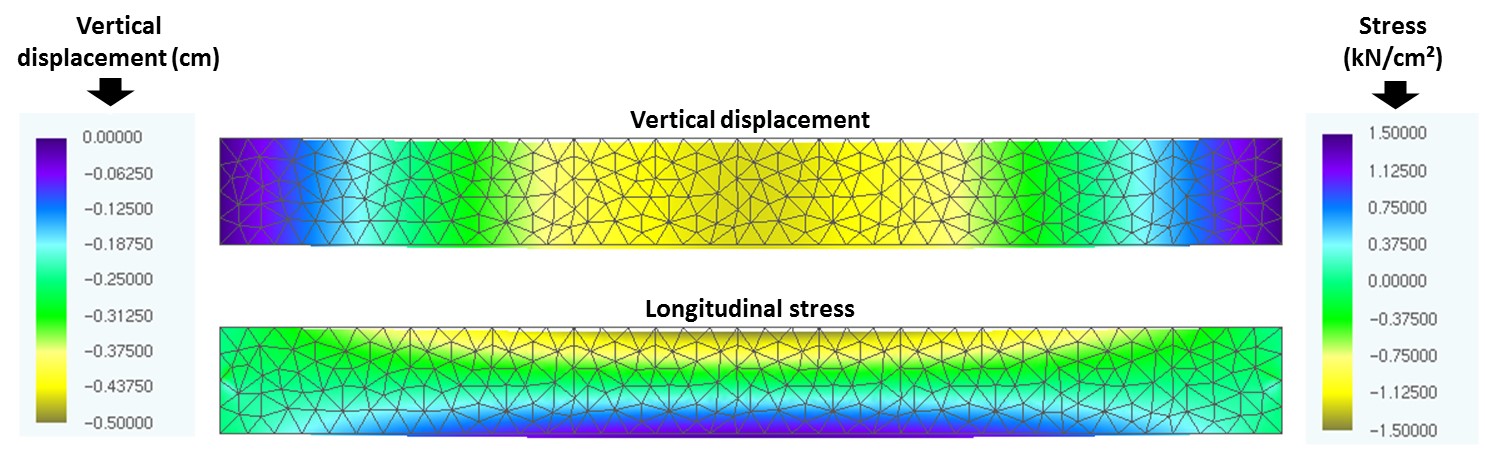
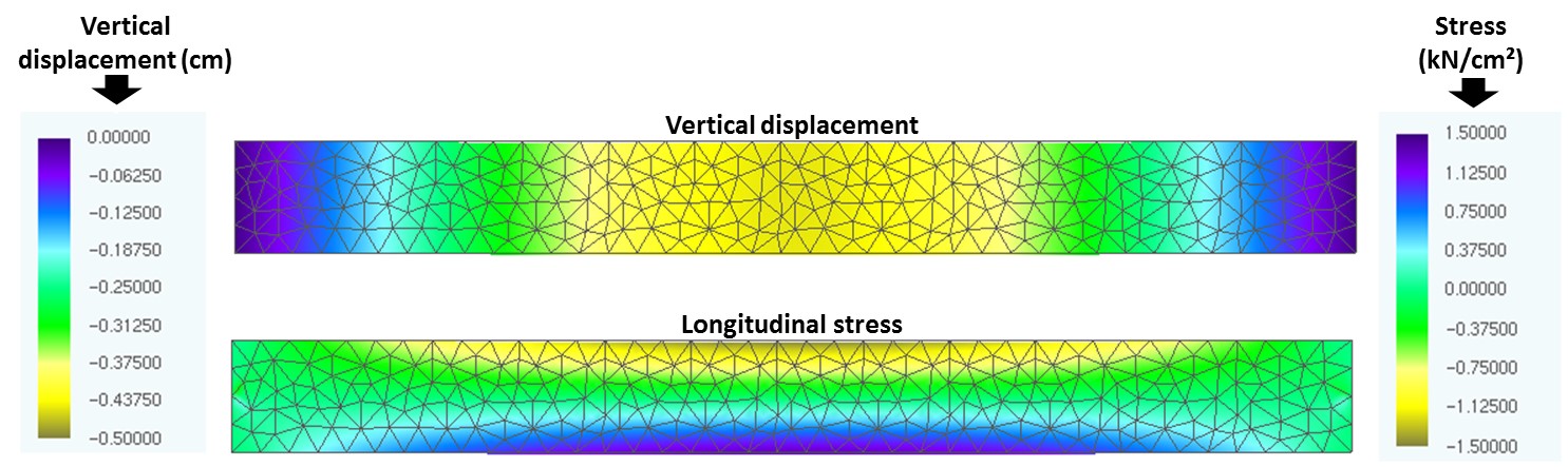
Thought the color maps presented in Figures 13, 14 and 15 it is possible to observe that the displacements of the beam decrease with the increase of the concrete cover because of the fact that there is a greater layer of concrete for the diffusion of CO2, delaying the corrosion beginning and, consequently, the degradation of the reinforcement, responsible for giving greater rigidity to the concrete beam. This result demonstrates the need to know correctly the environment to which the structure will be exposed, since the concrete elements will be designed with the required durability, guaranteeing the design life of the structures and the safety of their users.
5. CONCLUSIONS
From the analysis of the presented results regarding the validation of the developed model, it can be concluded that the formulation for the determination of the Design Life (DL) through the use of Artificial Neural Networks (ANN) and the formulation for the mechanical analysis of reinforced concrete structures under uniform corrosion based on the Finite Element Method (FEM) are consistently implemented and present consistent results when compared to literature data.
From the simulations performed with the model generated by the coupling of the MEF with the ANN, it was possible to conclude that:
· An adequate concrete cover (cover which takes into account the degree of aggressiveness to which the structure is exposed) guarantees not only a longer period to lead to the depassivation of the reinforcement, but also to reach the crack-opening limit recommended by NBR 6118 (ABNT, 2014);
· Consideration of the loss of steel mass as a consequence of corrosion results in the development of cracks larger than the recommendation of the NBR 6118 (ABNT, 2014), when the level of corrosion reaches 60 %;
· When the corrosion rate of the reinforcement reaches 50%, there is an increase of 30% in the beam vertical displacement, regardless of the concrete cover;
· By increasing the concrete cover, the maximum displacements and the deformation of the beam are reduced at the end of the DL, due to the lower degree of corrosion to which the reinforcement is subjected;
· Although all the beams at the end of the DL are with the concrete in the same state of cracking, the mechanical capacity of the beam with 30 mm of concrete cover is higher than the others beams, since the reinforcement has a lower degree of corrosion and a greater area of steel, demonstrating that a concrete cover coherent with the aggressiveness of the environment to which the structure is exposed provides durability and security for its users.
The results obtained indicate the applicability of the developed code as an efficient and alternative tool for the analysis of the design life of reinforced concrete structures subjected to uniform corrosion.
In addition, the developed program demonstrates the efficiency of the use of numerical tools in the development of models for the study and simulation of complex mechanisms of the degradation of reinforced concrete structures, corroborating with the studies of the pathology of constructions.
Acknowledgements
Authors thanks the Coordination of Personal Improvement of Higher Education (CAPES) and to the National Council of Scientific and Technological Development (CNPq) by the financial support.
7. REFERENCIAS
Andrade, C. (1992), “Manual para diagnóstico de obras deterioradas por corrosão de armaduras”, Tradução de Antônio Carmona e Paulo Helene, São Paulo: PINI, p. 104.
Andrade, J. J. O., Possan, E., Dal Molin, D. C. C. (2017), “Considerations about the service life prediction of reinforced concrete structures inserted in chloride environments”, Journal of Building Pathology and Rehabilitation, V. 2, p. 1-8.
Associação Brasileira de Normas Técnicas (2014), NBR 6118 - Projeto de estruturas de concreto, Rio de Janeiro, ABNT.
Bakker, R. M. F. (1988), Initiation period. In: Schiess P. “Corrosion of steel in concrete”, London, Chapman and Hall, cap. 3, pp. 22-55.
Biondini, F., Frangopol D. M. (2017), “Time-variant redundancy and failure times of deteriorating concrete structures considering multiple limit states”, Structure and Infrastructure Engineering, V.13, pp. 94-106.
Bob, C., Afana, E. (1993), “On-site assessment of concrete carbonation”, Proceedings of the International Conference Failure of Concrete Carbonation, RILEM, Bratislava, pp. 84-87.
Broomfield, J. P. (2007), “Corrosion of steel in concrete: understanding, investigation and repair”. 2. Ed. New York, Taylor & Francis, pp. 294.
Carmona, A. F., Marega, A. (1988), “Retrospectiva da patologia no Brasil: Estudo Estatístico”, in: Jornadas em Español y Portugués sobre Estructuras y Materiales, CEDEX, IETcc, pp. 325-348.
Chang, C. F., Chen, J. W. (2006), “The experimental investigation of concrete carbonation depth”, Cement and Concrete Research, V.36, pp. 1760-1767.
Coda, H. B. (2003), “Análise não linear geométrica de sólidos e estruturas: uma formulação posicional baseada no MEF”, Volume II, Departamento de Estruturas, Escola de Engenharia de São Carlos, Universidade de São Paulo, São Carlos.
Comission Permanente del Hormigón, EHE (2008), “Instrucción de Hormigón Estructural. Ministério de obras públicas e urbanismo”. Madrid, Espanha.
Dal Molin, D. C. C. (1988), “Fissuras em estruturas de concreto armado: análise das manifestações típicas e levantamento de casos ocorridos no Estado do Rio Grande do Sul”, Dissertação de Mestrado em Engenharia, Universidade Federal do Rio Grande do Sul, Porto Alegre.
Dyer, T. (2015), “A durabilidade do concreto”. Rio de Janeiro, Editora Ciência Moderna, pp. 536.
Ellingwood, B. R., Frangopol, D. M. (2016), “Introduction to the state of the art collection: risk-based lifecycle performance of structural systems”, Journal of Structural Engineering, V.142, pp. 1.
Felix, E. F. (2016), “Desenvolvimento de software para a estimativa da profundidade de carbonatação, vida útil e captura de CO2 de estruturas de concreto empregando RNA’s”, Trabalho de conclusão de curso, Universidade Federal da Integração Latino-Americana, Foz do Iguaçu.
Félix, E. F., Carrazedo, R., Possan, E. (2017), “Análise Paramétrica da carbonatação em estruturas de concreto armado via Redes Neurais Artificiais”, Revista ALCONPAT, V.7, N. 3, pp. 302-316.
Geiker, M. R., Polder, R. B. (2016), “Experimental support for new electro active repair method for reinforced concrete”, Materials and Corrosion, V.67, pp. 600-606.
Graeff, A. G. (2007), “Avaliação experimental e modelagem dos efeitos estruturais da propagação da corrosão em elementos de concreto armado”, Dissertação de Mestrado em Engenharia, Universidade Federal do Rio Grande do Sul, Porto Alegre.
Kari, O. P., Puttonen, J., Skantz, E. (2014), “Reactive transport modelling of long-term carbonation”, Cement and Concrete Composites, V.52, pp. 42-53.
Köliö, A., Pakkala, T. A., Hohti, H., Laukkarinen, A., Lahdensivu, J., Mattila, J., Pentti, M. (2017), “The corrosion rate in reinforced concrete facades exposed to outdoor environment”, Materials and Structures, V.50, pp. 1-16.
Mehta, P. K., Monteiro, P. J. M. (2014), “Concreto: microestrutura, propriedades e materiais”. 2.ed. São Paulo, IBRACON, pp.751.
Neville, A. M. (1997), “Propriedades do concreto”, São Paulo: PINI, pp. 828.
Possan, E. (2010), “Modelagem da carbonatação e previsão de vida útil de estruturas de concreto em meio urbano”, Tese de Doutorado em Engenharia, Programa de Pós-Graduação em Engenharia Civil, Universidade Federal do Rio Grande do Sul, Porto Alegre.
Rao, A. S., Lepech, M. D., Kiremidjian, A. S., Sun X. Y. (2017), “Simplified structural deterioration model for reinforced concrete bridge piers under cyclic loading”, Structure and Infrastructure Engineering, V.13, pp. 55-66.
Smolczyk, H. G. (1969), “Written Discussion”, proceeding of the 1969 International Symposium on the Chemistry of Cement, Part III, v. II/4, pp. 369-384.
Stewart, M. G., Rosowsky, D. V. (1998), “Structural safety and serviceability of concrete bridges subject to corrosion”, Journal of Infrastructure Systems V.4, pp. 146-155.
Tuutti, K. (1982), “Corrosion of steel in concrete”. Stockholm, Swedish Cement and Concrete Research Institute.
Val, D. V., Melchers, R. E. (1997), “Reliability of deteriorating RC slab bridges”, Journal of Structural Engineering, V.123, pp. 1638-1644.
Vesikari, E. (1988), “Service life prediction of concrete structures with regard to corrosion of reinforcement”. Technical Research Centre of Finland, report No. 553, Finland p. 53.
Vu, K. A. T., Stewart, M. G. (2000), “Structural reliability of concrete bridges including improved chloride-induced corrosion models”, Structural Safety, V.22, pp. 313-333.
Yanaka, M, Ghasemi, S. H., Nowak, A. (2016), “Reliability-based and life-cycle cost-oriented design recommendations for prestressed concrete bridge girders”, Structural Concrete, V.17, pp. 836-847.
Author notes
emerson.felipe.felix@gmail.com
Additional information
Cite
as: : E. F. Felix, T. J. Rodrigues Balabuch, M. Corrêa Posterlli, E. Possan,
R. Carrazedo (2018), “Service life
analysis of reinforced concrete structure under uniform corrosion through ANN
model coupled to the FEM”, Revista ALCONPAT, 8 (1), pp. 1 - 15. DOI: 10.21041/ra.v8i1.256
Legal Information: Revista ALCONPAT is a
quarterly publication of the Latinamerican Association of quality control,
pathology and recovery of construction- International, A. C., Km. 6, antigua
carretera a Progreso, Mérida, Yucatán, C.P. 97310, Tel.5219997385893, alconpat.int@gmail.com, Website: www.alconpat.org
Editor: Dr. Pedro Castro
Borges. Reservation
of rights to exclusive use No.04-2013-011717330300-203, eISSN 2007-6835, both
awarded by the National Institute of Copyright. Responsible for the latest update
on this number, ALCONPAT Informatics Unit, Ing. Elizabeth Sabido Maldonado, Km.
6, antigua carretera a Progreso, Mérida, Yucatán, C.P. 97310.
The views expressed by the
authors do not necessarily reflect the views of the publisher.
The total or partial
reproduction of the contents and images of the publication without prior
permission from ALCONPAT International A.C. is not allowed.
Any discussion, including
authors reply, will be published on the third number of 2018 if received before
closing the second number of 2018.